background image


One Digital Drive 

Novato, CA 94949 


Voice:  415-883-0128  Web:  www.sutter.com 
Fax: 

415-883-0572  Email: [email protected] 


TRIO

 MP-245A 


Three-Axis Motorized 

Micromanipulator System 

With Synthetic Fourth “D” Axis and  

USB Interface for External Control 


Operation Manual 

Rev. 3.12b (20191001)  

Summary of Contents for TRIO MP-245A

Page 1: ...ice 415 883 0128 Web www sutter com Fax 415 883 0572 Email info sutter com TRIO MP 245A Three Axis Motorized Micromanipulator System With Synthetic Fourth D Axis and USB Interface for External Control...

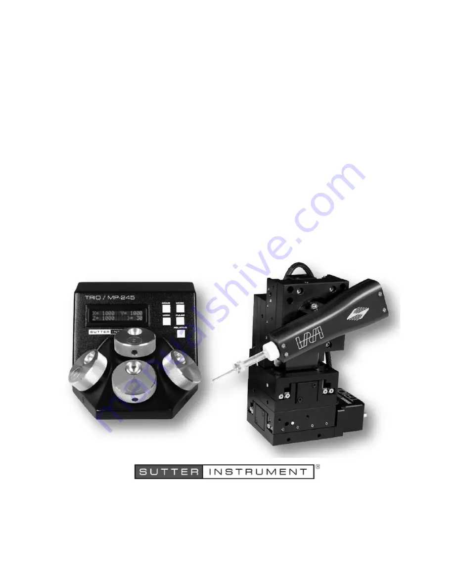
Page 2: ...age shows a TRIO MP 245A ROE controller and a TRIO MP 245 M micromanipulator The Sutter Instrument IPA Headstage shown mounted on the micromanipulator is not included in the TRIO MP 245A Series system...

Page 3: ......

Page 4: ......

Page 5: ...ays recommended NOTE There are no user replaceable fuses in the TRIO MP 245A system The TRIO MP 245A system s power supply consists of an external AC to DC switching power adapter If the external powe...

Page 6: ...art of the micromanipulator electromechanical device while it is in operation and moving Doing so can result in physical injury e g fingers can be caught and pinched between the moving parts of the mi...

Page 7: ...figuration 15 2 5 1 Power Switch 15 2 5 2 Rear Panel Configuration Switches 16 2 5 2 1 Rear Panel Switches 1 2 3 and 4 Knob Rotation Directionality for Forward Movement 16 2 5 2 2 Rear Panel Switch 5...

Page 8: ...Command 27 4 7 2 Move to Controller Defined HOME Position h Command 28 4 7 3 Move to Controller Defined WORK Position w Command 28 4 7 4 Move to Specified Home Position H Command 28 4 7 5 Move to Spec...

Page 9: ...Relative mode 22 Figure 3 10 Relative mode 22 Figure 3 11 Absolute mode 22 Figure 3 12 Angled side view of TRIO MP 245 M to change headstage mount 24 Figure 6 1 Locations of the axis connectors insid...

Page 10: ...ommand 31 Table 4 14 Move to specified Z axis position z or Z command 31 Table 4 15 Set the angle A command 32 Table 4 16 Recalibrate R command 32 Table 4 16 Straight Line Move S Command Speeds 34 Tab...

Page 11: ...TRIO MP 245A system Chapter 2 Installation which describes how to install set up and configure all components of the system Chapter 3 Operations which describes how to operate the TRIO MP 245A Chapte...

Page 12: ...pendent axes X Y and Z each with 25mm travel with a virtual fourth axis D for coaxial pipette movement utilizing a tangent function factoring the holder s angle and the X and Z axes Sub micron 100nm r...

Page 13: ...mode the display turns red and ROE input is locked out to avoid any accidental motion Pressing and holding the RELATIVE button for three seconds at any location causes the display coordinates to all z...

Page 14: ...12 TRIO MP 245A FOUR AXIS MICROMANIPULATOR SYSTEM OPERATION MANUAL REV 3 12B 20191001 This page intentionally left blank...

Page 15: ...adapter plate using four M3 5x6 hex head locking screws Figure 2 1 Side view of TRIO MP 245 M showing mounting adapter plate and lock screws The TRIO MP 245 M is shipped with the adapter plate in plac...

Page 16: ...fits into the dovetail not shown All the headstage adapters and mounting hardware are included with the manipulator and are shipped in a zip lock plastic bag 2 3 Other Accessories One or more accessor...

Page 17: ...ug receptacle 3 With the power OFF connect the male end of the DB 25 cable to the MANIPULATOR connector on the ROE the other end of which is connected to the TRIO MP 245 M micromanipulator electromech...

Page 18: ...ile homing Table 2 2 Rear Panel Configuration Switch 5 Y Axis Homing Movement Lock Out Rear Panel Switch Y Axis Homing Movement Lock Out Enabled Disabled 5 OFF Up ON Down Factory default recommended n...

Page 19: ...2 Electromechanical device compatibility Internal Switch Definition State Setting Position 2 Eletromechanical device compatibility MP 845 M MP 845S M MP 245 M series OFF UP MP 285 M series micromanipu...

Page 20: ...18 TRIO MP 245A FOUR AXIS MICROMANIPULATOR SYSTEM OPERATION MANUAL REV 3 12B 20191001 This page intentionally left blank...

Page 21: ...showing startup screen When starting the TRIO MP 245A system for the first time or if the HOME position has not yet been defined saved the values of all four axes will be 1 000 micrometers microns Fi...

Page 22: ...dovetail bracket rotate the holder to the desired angle and then retighten the set screw Measure the angle of the holder Tip Many smart phones have an app with a level that can assist the user 3 3 4...

Page 23: ...the movement will be as follows NOTE Movement to the Home position works only if X coordinates of the HOME position are less than the WORK position HOME and WORK positions cannot be the same 1 Moveme...

Page 24: ...reen To switch to relative coordinates press the RELATIVE button once To reset the current position to all zeroes depress the RELATIVE for 3 seconds or until a beep is heard and then release the butto...

Page 25: ...e Movements HOME while moving to Home After Move to Home has been initiated and while the move is in progress pressing HOME a second time pauses the manipulator Pressing HOME again resumes movement 3...

Page 26: ...loosen the screw in the center of the holding bracket Slide the headstage upward out of the dovetail groove Make any adjustments needed of the headstage and then tighten down but do not over tighten...

Page 27: ...troller over USB can be conducted 1 USB Direct D2XX mode or 2 Serial RS 232 asynchronous via the VCP device driver VCP mode The first method requires that the VCP device driver not be installed or if...

Page 28: ...version between microsteps and microns micrometers is the responsibility of the software running on the host computer see Microns microsteps conversion table for conversion factors Microsteps are stor...

Page 29: ...double precision floating point values Table 4 3 Ranges and bounds Device Axis Millimeters Microns Microsteps MP 845 M MP 845S M or MP 245 M micromanipulator X Y Z 0 25 0 25 000 0 266 667 MP 285 M mic...

Page 30: ...e to controller defined HOME position h command Tx Delay Rx Ver Total Bytes Byte Offset Len Value Alt key pad Ctrl char ASCII def char Description Dec Hex Binary Tx All 1 0 104 68 0110 1000 0104 h Com...

Page 31: ...mand 1 4 X steps 5 4 Y steps 9 4 Z steps Rx All 1 0 13 0D 0000 1101 M CR Completion indicator 4 7 6 Move in Straight Line to Specified Position at Specified Speed S Command This command instructs the...

Page 32: ...110728346 56 25 7 2 5000 2500 0 2500000 0 098425197 50 00 6 2 1875 2187 5 2187500 0 086122047 43 75 5 1 8750 1875 0 1875000 0 073818898 37 50 4 1 5625 1562 5 1562500 0 061515748 31 25 3 1 2500 1250 0...

Page 33: ...er Total Bytes Byte Offset Len Value Alt key pad Ctrl char ASCII def char Description Dec Hex Binary Tx All 5 0 121 or 91 79 or 5B 0111 1001 or 0101 1011 0121 or 0091 y or Y Command 1 4 Y steps Rx 1 0...

Page 34: ...sending a command sequence and before sending the next command 3 Clearing Send Receive Buffers Clearing purging the transmit and receive buffers of the I O port immediately before sending any command...

Page 35: ...LabVIEW always handles byte strings in Big Endian byte order irrespective of operating system and CPU requiring that the four bytes containing a microsteps value be reverse ordered before after conve...

Page 36: ...8750 1875 0 1875000 0 073818898 37 50 4 1 5625 1562 5 1562500 0 061515748 31 25 3 1 2500 1250 0 1250000 0 049212598 25 00 2 0 9375 0937 5 937500 0 036909449 18 75 1 0 6250 0625 0 625000 0 024606299 12...

Page 37: ...ect all cables and connections to make sure that all connections are made well and that all connectors are well and evenly seated 6 RECONFIGURATION 6 1 Changing the Rotary Knob Functions on the ROE Co...

Page 38: ...36 TRIO MP 245A FOUR AXIS MICROMANIPULATOR SYSTEM OPERATION MANUAL REV 3 12B 20191001 This page intentionally left blank...

Page 39: ...buse misuse or unauthorized repairs will void this warranty Warranty work will be performed only at the factory The cost of shipment both ways is paid for by Sutter Instrument during the first three m...

Page 40: ...for rod OD 2 4mm MP ROD Rod holder for rod OD 6 25 mm or larger MP RISER 0 5 inch riser MP RISER 1 0 1 inch riser1 MT 78 FS Large fixed stage platform MT 78 FS M6 Large fixed stage platform with M6 ta...

Page 41: ...ontroller Rear Panel Port Connector Receptacle Cable Connector Types Connects to Cable Type Cable Max Length Power Adapter 3 pin male connector 3 pin power standard female 3 pin male Geographical regi...

Page 42: ...40 TRIO MP 245A MICROMANIPULATOR SYSTEM QUICK REFERENCE REV 3 12B 20191001 FW V3 12 Weight TRIO MP 245A ROE controller 2 3 lbs 1 04 kg TRIO MP 245 M micromanipulator 3 5 lbs 1 6 kg...

Page 43: ...nal 1 4 Switch 3 OFF up for MP 845 S M MP 245 M ON down for MP 285 M related devices 3DMS MT 78 MOM SOM objective movers Contact Sutter Instrument tech support for more information Sw Definition State...

Page 44: ...eted indicator Command Sequence Formatting Each command sequence consists of at least one byte the first of which is the command byte Those commands that have parameters or arguments require a sequenc...

Page 45: ...e precision floating point values Table D 5 Ranges and bounds Device Axis Len mm Origin Microns Micromet ers m Microsteps steps MP 845 M MP 845S M or MP 245 M micromanipulator X Y Z 25 BOT 0 25 000 0...

Page 46: ...s 5 4 Y steps 9 4 Z steps Rx All 1 0 13 0D 0000 1101 M CR Completion indicator Move in Straight Line to Specified Position at Specified Speed S Tx All 14 0 83 53 1001 0111 0083 S Move all three axes s...

Page 47: ...lute vs Relative Positioning Current position c and move commands always use absolute positions All positions can be considered relative to the Origin Position 0 but all are in fact absolute positions...

Page 48: ...5000000 0 196850394 100 00 14 4 6875 4687 5 4687500 0 184547244 93 75 13 4 3750 4375 0 4375000 0 172244094 87 50 12 4 0625 4062 5 4062500 0 159940945 81 25 11 3 7500 3750 0 3750000 0 147637795 75 00 1...

Page 49: ...mplete indicator 34 external control intercommand delay 34 external control clearing send receive buffers 35 external control positions in microsteps 35 external control ranges and bounds 35 external...

Page 50: ...Switch 1 Reserved 17 Switch 3 Reserved 18 Switch 4 Linear nonlinear manual operation 18 internal configuration Switch 2 electromechanical type 18 internal configuration switches 17 linear nonlinear m...

Page 51: ...ging rotary knob functions on the ROE 39 Reserved configuration switches internal 1 3 17 18 S safety warnings mains fuse 3 safety warnings precautions operational 4 SAFETY WARNINGS PRECAUTIONS 3 elect...

Page 52: ...50 TRIO MP 245A MICROMANIPULATOR SYSTEM QUICK REFERENCE REV 3 12B 20191001 FW V3 12 NOTES...

Reviews: