17
DLD8080 R4.30 & R4.31 Manual
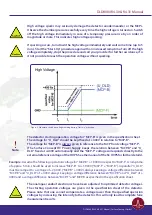
Figure 5: Schematic sketch on voltage ramping with external reference voltage.
Note
The detector starting operation voltage for “MCP-B” is given in the specification sheet.
The voltage for “U_DLD” should be kept fixed at +400V in relation to “MCP-B” .
The voltage for “MCP-B” is always given in reference to the MCP front voltage “MCP-F”.
(The Surface Concept HV Power Supply keeps the relation between “MCP-B” and “U_
DLD” fixed at +400V automatically and the “MCP-F” voltage corresponds directly to
the external reference voltage of the HVPS. See the manual of the SC HVPS for further
details).
Example:
Assume the following operation voltage for “MCP-B”: +1,900V in respect to “MCP-F” and a
reference voltage for “MCP-F” of -500V. A ramp time of approx. 1.3min should be used to increase “MCP-F”
to -500V. Then a ramp time of 5 min. should be used to increase “MCP-B” to +1,400V (“MCP-F” + “MCP-B”).
In parallel “U_DLD” must be ramped to a voltage of +1,800V (“MCP-B” +400V), always keeping a voltage
difference between “MCP-B” and “U_DLD” of +400V and a voltage difference between “MCP-F” and “MCP-B
as specified in the specification sheet.
The “MCP-B” voltage is always given in reference to the “MCP-F” voltage. For a proper
operation of the DLD we highly recommend to use a HV supply which can float on an
external reference voltage. In this case one can provide the MCP operation voltage
directly floating on the “MCP-F” potential by connecting the “MCP-F” potential to the
DLD head as well as to the HV supply as external reference voltage. This ensures that in
case of a voltage drop of the “MCP-F” potential also the operation voltage is driven down
in parallel. This prevents that dangerous voltage differences at the detector head can
occur. The same we recommend for the supply of the “U_DLD” potential.
DLD8080 R4.30 & R4.31 Manual | Surface Concept GmbH


