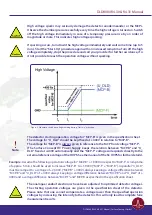
24
6 Delayline Detector Layout
6.1 Delayline Detector - Vacuum Wiring
The Delayline Detector DLD8080 R4.30 & R4.31 consists of a round detection area, defined by the MCP
holders and the detector cover. The detector anode consists of two meander structured delaylines (named
X and Y), which are placed above each other (electrically isolated) and are orientated perpendicular to
each other. The one delayline is referred to as the X meander and the other delayline as the Y meander.
gives a schematic orientation of the X and Y meanders.
Signal readout is done via two readout lines (named 1 and 2) for each meander-structured delayline.
The naming of the readout lines is put together of the naming of the meander structured delayline X and
Y and the naming 1 and 2 of the individual readout lines per delayline (e.g. X2 for the second line of the X
meander).
The 0/0 position of the DLD image (top left corner of displayed image in the GUI software) is marked by a
black dot.
Image 0/0 position
Figure 9: Schematic orientation and naming of delaylines and DLD image.
sensitive direction
sensitiv
e dir
ec
tion
y meander
x meander
DLD8080 R4.30 & R4.31 Manual | Surface Concept GmbH


