SurePoint SENTINEL Manual Download Page 43


396

-

5477Y1 Sentinel Row Control Manual


        ©2022 SurePoint Ag Systems             41


     4/29/2022


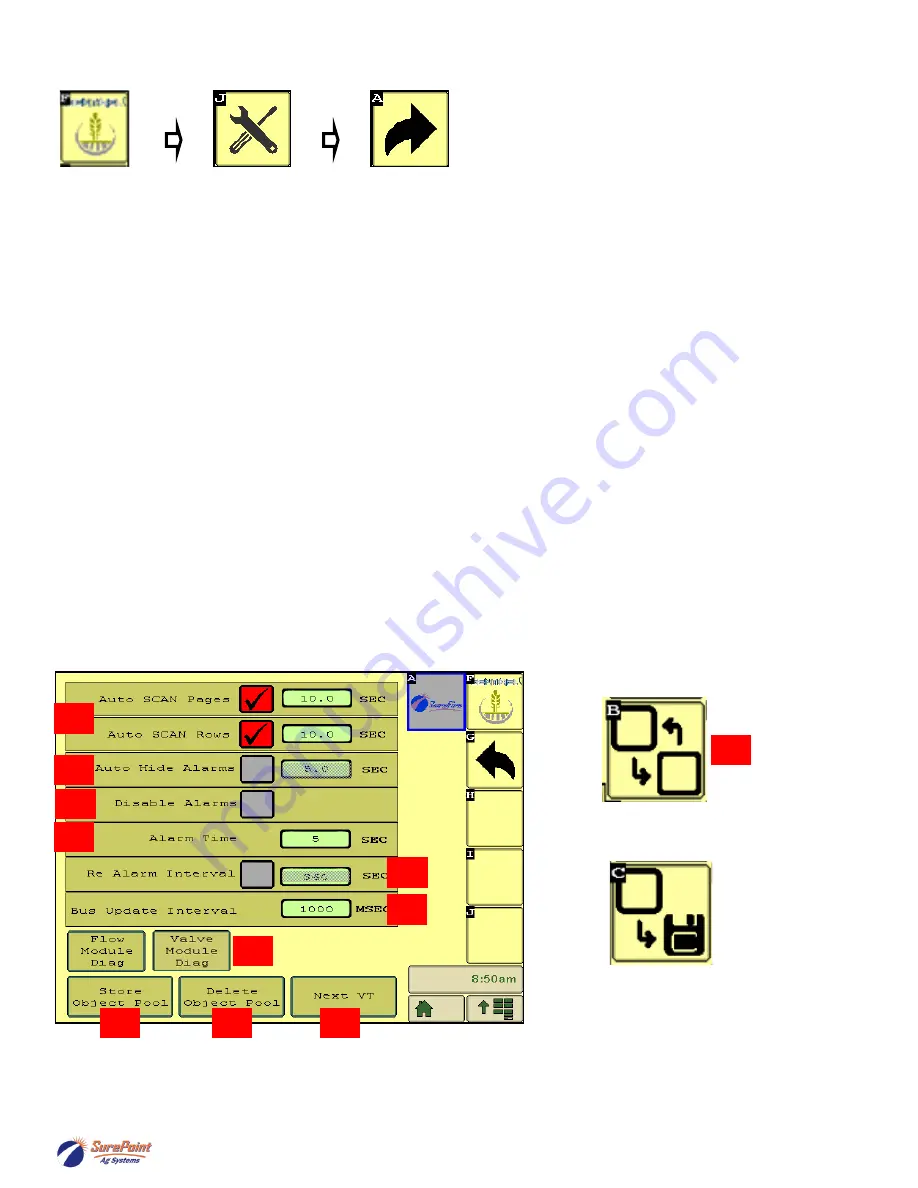
Customizing Scans & Alarms, etc


This screen allows the user to change how row information is displayed on the HOME screen.  


35.)  When checked, the 

Auto  Scan 

feature will scan through the product pages  and/or rows on the HOME 

screen.  You can change the length of time it stays on each page or row before advancing.


36.)  

Auto Hide  Alarms (if checked) 

sets how long full

-

page alarms are displayed before they go away (see 

pg. 20) 


37.)  

Disable Alarms


-

 Check this to turn off alarms. May want to do this for testing or troubleshooting.


38.)  

Alarm Time 

-

 how long a row must be outside of the specified tolerance before the alarm sounds

.


39.  Re  Alarm Interval 

-


The time before the Alarm alarms again after being acknowledged. If the issue that 

triggered  the  alarm  is  not  resolved,  it  will  keep  alarming  at  this  interval  until  resolved  (if  the  box  is 
checked).


40.  

Bus  Update  Interval 

-


Use this to slow down ISOBUS traffic if the BUS load is too high. 

Reset only after 

talking to a SurePoint representative.


41.) 

Flow  Module  Diagnostics 

and 

Valve  Module  Diagnostics

-

 These are addressed on previous page. 

Press one of these to go the Module Addressing screen.


42.)  

Store Object Pool 

-

 Stores the current ISOBUS layout on the VT.


43.)  

Delete Object Pool 

-

 Deletes the current object pool on the VT and forces the monitor to regenerate the 

display when it is rebooted. This may be necessary after a software update or feature unlock or if some 
screens or features do not appear correct.


44.)  

Next  VT 

-

 press to push Sentinel to another virtual  terminal. This may be necessary if there is more 

than one monitor or display in the cab.


35


37


36


40


39


38


44


43


42


41


Next VT 

icon from v.1.3.0


Save to this VT

 from v.1.3.0


44


SurePoint 

Ag 

Systems

Summary of Contents for SENTINEL

Page 1: ...396 5477Y1 Sentinel Row Control Manual 2022 SurePoint Ag Systems 4 29 2022 396 5477Y1 Installation Guide Operator s Manual S u r e P o i n t A g S y s t e m s ...

Page 2: ...396 5477Y1 Sentinel Row Control Manual 2022 SurePoint Ag Systems 4 29 2022 S u r e P o i n t A g S y s t e m s ...

Page 3: ...tment 2 product setup 39 37 Flow Module Addressing and Valve Module Addressing 40 Customizing Scans and Alarms Flow Module Diagnostics 41 Setup Settings for Row Control Control Speed Flow Cal PWM Max 42 Valve Setup and Row Detail Screen 43 Software Version Auxiliary Settings Feature Unlock Code 44 Customizable Toolbar Totalizer Counters 45 Row Control Run Screen and Operation and Setup Summary 46 ...

Page 4: ...NGER Indicates an imminently hazardous situation that if not avoided will result in death or se rious injury This signal word is to be limited to the most extreme situations typically for machine components which for functional purposes cannot be guarded WARNING Indicates a potentially hazardous situation that if not avoided could result in death or serious injury and includes hazards that are exp...

Page 5: ...ing pressure to the system Use a piece of paper or cardboard NOT BODY PARTS to check for sus pected leaks Wear protective gloves and safety glasses or goggles when working with hydraulic systems DO NOT DELAY Check hydraulic hoses and fittings frequently Loose broken and missing hardware can cause equipment to not perform properly and can result in serious injury or death Hydraulic systems can be h...

Page 6: ...T3 Tee 5 120 T3MPLUG T3 Male FC Plug 6 124 02 010004 T4 Fork 7 120 T4FT3FRC T4 Female x T3 Female FC Reducer Coupling 8 120 T4MT3MRN T4 Male x T3 Male FC Reducer Nipple 9 121 T3M075 90 T3 Male FC x 3 4 HB 90 degree 10 121 T3F075 T3 Female x 3 4 HB 11 124 01 G11056 V Viton O Ring for T1 fittings 12 124 01 G11058 V Viton O Ring for T3 fittings 13 124 01 G11054 V Viton O Ring for T4 fittings See next...

Page 7: ...t Number Description 120 T1M038QC T1 Male x 3 8 QC 120 T1M025QC T1 Male x 1 4 QC 121 T1M038 T1 Male x 3 8 HB 121 T1M050 T1 Male x 1 2 HB 124 01 G11056 V Viton O ring for T1 Fittings Part Number Description 204 01 4625AAGB1B1 4 Row Sentinel flow meter 124 02 010001 T1 Fork 374 4024Y1 4 Pin Amp Superseal dust plug 384 1105 Hardware Kit mounting bolts T1 Fittings Commonly used Quick Connect QC Fittin...

Page 8: ... carries ISOBUS Y harnesses to split the ISO connection at the tractor Service Connections The Terminating Resistor Programming and RS232 connectors are for service only and should not be used Bus Connections 2 Bus connections are provided for convenience so that each side of the implement can plug into the ECU har ness without the need for a long continuous chain of connections Implement Height a...

Page 9: ...through the port labeled 12Vdc while the remaining port is plugged CAN connections cannot be left open When a terminator is removed to plug in a trunkline the terminator must be moved to the end of the trunkline It is not required to utilize both Bus connections on the main harness If Meter Bus 2 is not used plug a terminator in to that connector Add 4 pin Extension where needed 206 04 XXXX CAN tr...

Page 10: ...ing process VALVE A B C D Connect to the correct row control valve match A B C D with the Sentinel Flowmeter module plumbing for each row Sentinel Row Control Valve Interface 226 01 4211Y1 Sentinel Flowmeter Module 204 01 4625AAGB_B_ CANBUS Connect to Trunkline during Module addressing process Connect to Valves A B Connect to Valves C D Individual Row Control Valve S u r e P o i n t A g S y s t e ...

Page 11: ... the valve interface assembly to the Sentinel Row Monitoring mounting bracket using hardware kit 384 1130 3 8 hex head bolt and flange nut 4 Mount the Sentinel Row Monitor flowmeter module to the mounting bracket using hardware kit 384 1105 5 16 hex head bolts and flange nuts See plumbing assembly next page It may be desired to assemble plumbing prior to mounting to the bracket 5 Route CAN trunkli...

Page 12: ... T3MPLUG into the end of the manifold Secure with fork fitting 4 Install the female 3 4 hose barb elbow fitting 121 T3F075 90 onto the inlet of the manifold Secure with fork fitting 5 Insert the outlet 3 8 hose barb fitting 121 T1M038 into the bottom ports of the flowmeter and secure with fork fitting Lubricate all o rings prior to installation to prevent rolling stretching or tearing the o ring a...

Page 13: ...y across the toolbar in the center of every 4 rows if possible 4 Route the 3 4 supply hose to the inlet port of the Sentinel Row Monitor Flowmeter Module manifold 5 Route 3 8 OD tubing or 3 8 hose from the Sentinel Flowmeter Module to the Sentinel Row Control Valve located near the row unit Avoid pinch points on the planter and allow for row unit travel Note Lubricate 3 8 tube or tube fitting and ...

Page 14: ...mpRight PR17 PR30 or 1 x 3 4 Hose Barb Tee PR40 D250 3 4 Hose Barb Tee PumpRight PR17 PR30 or 1 x 3 4 Hose Barb Tee PR40 D250 527 16 100100 16 Row Sentinel Row Control Plumbing Kit 527 24 100100 24 Row Sentinel Row Control Plumbing Kit ROW PLUMBING CONFIGURATIONS S u r e P o i n t A g S y s t e m s ...

Page 15: ...30 or 1 x 3 4 Hose Barb Tee PR40 D250 527 32 100100 32 Row Sentinel Row Control Plumbing Kit PR17 PR30 Kit 527 32 100200 32 Row Sentinel Row Control Plumbing Kit PR40 D250 PR80 Kit 527 36 100100 36 Row Sentinel Row Control Plumbing Kit PR17 PR30 Kit 527 36 100200 36 Row Sentinel Row Control Plumbing Kit PR40 D250 PR80 Kit ROW PLUMBING CONFIGURATIONS S u r e P o i n t A g S y s t e m s ...

Page 16: ...nt 2 valves to the same bracket for dual product system or reduced toolbar install footprint Valve Mounting Options Sentinel Row Control Valve Installation 1 Mount the Sentinel Row Control valve and mounting bracket to the planter using one of the kit options below 2 Route 3 8 OD tubing or 3 8 hose from the Sentinel Flowmeter Module to the row unit Avoid pinch points on the planter and allow for r...

Page 17: ...ction 6 15 16 In 17 Pr Pressure 3 17 Out 10 PWM2 18 In 23 F1 19 Out 19 Section 15 20 Out 15 Section 11 21 In 28 Spare 22 23 Out 24 LSB P2 24 25 Ignition SP 010 WB 043 SHT 4 5D WB 105 SHT 5 3D RD 18 WB 017 SHT 3 5C WB 044 SHT 4 5D WH YE 18 WB 045 SHT 4 5C WB 027 SHT 2 5B YE 18 RD 14 WH 18 RD 18 WB 063 SHT 5 5B WB 075 SHT 5 3B RD 18 BL WH 18 YE 18 Add 208 06 2912Y1 B D A C 1 2 3 4 5 6 Part 1 of 4 Se...

Page 18: ...9 Out 16 Section 12 40 41 In 25 B1 42 Out 25 Section 17 43 Out 21 LSA P1 44 RS232 TxD 45 ISOBUS CAN2 High 46 CAN4 High 47 48 In 12 Spare 49 In 8 P1 Flow 50 In 4 Right Speed GN 18 1 12V X 040 P Programming DT04 4P 2 CAN H 3 GND 4 CAN L WB 005 SHT 4 4D BK 18 GN 18 YE 18 WH BL 18 WB 069 SHT 5 3B BR 18 WB 047 SHT 4 5C WB 025 SHT 3 2B WB 011 SHT 4 2C WB 027 SHT 1 2B A TX X 033 R RS232 12010717 B RX C G...

Page 19: ...4 53 54 In 19 AI7 55 Out 12 PWM4 56 57 In 21 P1 RPM 58 Out 17 Section 13 59 Out 13 Section 9 60 In 26 B2 61 Out 26 Section 18 62 Out 22 LSB P1 63 RS232 RxD 64 ISOBUS CAN2 Low 65 CAN4 Low 66 67 In 13 LS Pressure 1 68 In 9 P2 Flow 69 In 5 PWM 1 70 In 1 Imp Switch 71 Out 7 Section 7 72 Out 8 Section 8 73 In 20 AI8 74 in 16 Pr Pressure 2 75 Out 9 PWM1 WB 035 SHT 4 4A WH BR 18 WH BL 18 BK 18 WB 017 SHT...

Page 20: ...BK 8 SP 009 WB 011 SHT 2 2B BK 14 RD 8 OR WH 18 SP 007 RD 14 RD 8 YE 18 BK 18 YE 18 YE 18 YE 18 1 ECU GND X 04 5 I ISO 776438 1 2 ECU Power 3 GND 4 ISO CAN High 5 6 Master Switch 7 8 12V Battery 9 Power 10 ISO CAN Low 11 12 1 ECU GND X 04 4 I ISO 776437 1 2 ECU Power 3 GND 4 ISO CAN High 5 6 Master Switch 7 8 12V Battery 9 Power 10 ISO CAN Low 11 12 1 HC GND X 047 P Power 19433 0014 2 HC PWR BK 18...

Page 21: ...ection 6 WB 091 SHT 6 5C OR 18 BK 14 BK 14 GN 18 WH GN 18 WH BK 18 WB 059 SHT 2 2A BR WH 18 A HC PWR 1 X 006 S Section 7 12 HDP24 18 14PE B HC PWR 2 C HC GND 1 D HC GND 2 E PWM 2 F PWM 2 G Pressure 2 WB 079 SHT 4 2A H Flow Return Valve 2 J Section 7 K Section 8 L Section 9 M Section 10 N Section 11 P Section 12 WB 105 SHT 1 2C SP 001 SP 015 RD 18 RD 18 WH BK 18 VT 18 SP 023 VT WH 18 VT WH 18 VT 18...

Page 22: ...ND 1 D HC GND 2 E F G H J Section 13 K Section 14 L Section 15 M Section 16 N Section 17 P Section 18 WH GN 18 WH 18 GN 18 BK 14 WH GN 18 GY 18 BK 14 GN 18 WB 087 SHT 5 2B BK 14 B A 1 2 3 4 5 6 Deutsch 14 pin 6HQWLQHO 5DWH 5RZ RQWURO 8 DUQHVV 3URGXFW 6HFWLRQV 6HFWLRQ RQQHFWRUV Y EHWZHHQ DQG Y EHWZHHQ ZKHQ 3 0 XW FOH LV Y EHWZHHQ 6HFWLRQ DQG URXQG ZKHQ YDOYH VKRXOG EH 21 396 5477Y1 Sentinel Row Con...

Page 23: ...te Control and Row Control Valve A Valve B Gray YEL OR WH WHT Flowmeter Bus 1 2 ISO Connector 12 pin General Diagnostic Tips 12 396 5477Y1 Sentinel Row Control Manual 2022 SureFire Ag Systems 21 2 15 2022 S u r e P o i n t A g S y s t e m s ...

Page 24: ... TOWER 4 PIN BLK RED 2 CAN Device 3 GRN 4 12VDC CAN L CAN H WHT 1 GND AMP SUPER SEAL TOWER 4 PIN BLK RED 2 CAN Device 3 GRN 4 12VDC CAN L CAN H WHT 1 DEUTSCH 4 PIN SHROUD BLK GRN 2 CAN Bus 3 GND CAN L CAN H WHT 4 12VDC RED DQG ZLWK RQH HYLFH FRQQHFWRU DQG ZLWK WZR HYLFH FRQQHFWRUV LV VLPLODU WR WKH DERYH EXW ZLWK WKUHH HYLFH FRQQHFWRUV DQG DUH VLPLODU WR WKH DERYH EXW ZLWK IRXU HYLFH FRQQHFWRUV 7K...

Page 25: ...o 9 PIN Deutsch HDB36 24 91SN 059 GND RED 14 AWG BLK DUST CAP DEUTSCH HDC34 24 A B ECU GND 12 V Batt BLK 14 AWG RED 14 AWG 3 PIN DEUTSCH HD16 3 96S Master Switch Connector Master Switch C DUST CAP DEUTSCH HDC14 3 JDL BLU SLQ 62 FRQQHFWRU Y EHWZHHQ Y EHWZHHQ Y EHWZHHQ Y EHWZHHQ 0DVWHU 6ZLWFK RU WHVWLQJ RU IRU HPHUJHQF XVH RX FDQ MXPS EHWZHHQ WR DFWLYDWH 0DVWHU 6ZLWFK Y EHWZHHQ SLQ 0ROH 3RZHU Y EHWZ...

Page 26: ...er Item Description 3 x 3 380 1022 1 2 U bolt Kit 1 2 fits 3 x 3 tube 3 opening 4 x 4 380 1023 1 2 U bolt Kit 1 2 fits 4 x 4 tube 4 opening 4 x 6 380 1015 1 2 U bolt Kit 1 2 fits 4 x 6 tube 4 opening 4 x 7 380 1039 1 2 U bolt Kit 1 2 fits 4 x 7 tube 4 opening 5 x 7 380 1014 1 2 U bolt Kit 1 2 fits 5 x 7 tube 5 opening 6 x 4 380 1017 1 2 U bolt Kit 1 2 fits 6 x 4 tube 6 opening 6 x 7 380 1018 1 2 U...

Page 27: ...de to check for proper hydraulic operation Override will completely open valve so limit tractor hydraulic flow to valve May need to clean packed dirt to allow movement of override knob Push down and turn 1 2 turn CW to return to operating position Hydraulic oil under extremely high pressure Do not use hand or any other skin to check for or to stop hydraulic leaks Be sure pressure is relieved befor...

Page 28: ...n If using this method the SurePoint PWM bypass valve must be open see previous page for instruction picture If bypass is left closed the SurePoint valve will limit the speed of the seed distribution fan For example the John Deere CCS fan uses around 7 GPM of oil This will limit the PumpRight maximum flow 8 GPM oil necessary for maximum flow See the charts on the next page for adjusted maximum pum...

Page 29: ... at a maximum of 550 RPM Spinning the pump over 550 RPM may cause pump failure The system will spin the pump faster than that if precautions are not taken to limit the speed This could happen if the strainer becomes plugged or blocked and the controller attempts to speed the pump up to achieve the desired Rate It could also happen if a high pressure situation occurs that opens the Pressure Relief ...

Page 30: ...hown above the flowmeter may be mounted directly to the PumpRight pump The flowmeter outlet is a 1 hose barb The outlet hose should be a minimum of 24 long with a gentle curve prior to any fittings for optimum flowmeter performance The flowmeter outlet will attach to your manifold s or section valves A 3 4 hose barb is included in the bag of parts and can be substituted on the flowmeter outlet Pre...

Page 31: ...y to the flowmeter with 1 1 2 hose As shown above the flowmeter may be mounted directly to the PumpRight pump The flowmeter outlet is a 1 1 2 hose barb The outlet hose should be a minimum of 24 long with a gentle curve prior to any fittings for optimum flowmeter performance The flowmeter outlet will attach to your manifold s or section valves Pressure Relief Valve PRV The PRV is a 100 psi relief I...

Page 32: ... in Left Area above On first bootup VT Up load may take several minutes for a new device Press ISOBUS to go to ISOBUS devices or Press the Senti nel icon to go to the Sentinel screens PRESS ISO to go to the ISOBUS VT screens There may be more than one ISOBUS device connected ISOBUS VT Menu There may be more than one ISOBUS device connected How to get to Sentinel on the VT or UT S u r e P o i n t A...

Page 33: ...396 5477Y1 Sentinel Row Control Manual 2022 SurePoint Ag Systems 31 4 29 2022 How to get to Sentinel on the VT or UT Trimble TMX 2050 Ag Leader InCommand S u r e P o i n t A g S y s t e m s ...

Page 34: ...ls set up products devices rows sections ROW BAR see Sentinel row graphs depicting the flow on each row SurePoint see software version Go to Auxiliary Settings screen Next VT when more than one display is in use this moves the Sentinel to the next screen v 1 3 0 Save to this VT when more than one display is available v 1 3 0 Nozzle Test Run a test with a simu lated speed and target rate v 1 3 0 Ca...

Page 35: ...ring ECU Harness 2 products 18 sections 208 06 4099Y4 Sentinel Row Control and Flow Monitoring ECU Harness 2 products 18 sections 208 06 4984Y2 Sentinel Row Control and Flow Monitoring ECU Harness 4 products 18 sections 208 06 4504Y1 Sentinel Row Control Valve 226 01 3547Y1 Sentinel ISOBUS ECU Typically will use one of the following Sentinel ECU Harnesses For Row Control S u r e P o i n t A g S y ...

Page 36: ... Set up the implement dimensions by touching the IMPLEMENT button 9 Choose a speed source by selecting the SPEED button 10 Select system control options task control lift switch etc under HARDWARE 11 Select the Rate Mode USER DEF at RATE SETUP 12 From the Settings screen touch the NEXT arrow 13 Click on Flow Module Diagnostics 14 Ensure that all flow modules are plugged in and click Reset All Addr...

Page 37: ...s may vary Sentinel Setup and Configuration 22 If applicable address the modules for product 2 by repeating the above steps for product 2 23 Customizing Scans and Alarms 24 Setup settings for Rate Control Control Speed Flow Cal PWM Max and Min 25 Valve Setup and Row Detail Screen 26 Software Version and Auxiliary Settings Screens 27 Customizable Toolbar and Totalizer Counters 28 Row Control Row Mo...

Page 38: ... 3 Press the big Product 1 box If the system has two products there will be a Product 2 box to the right of Product 1 Set up Product 2 in a similar fashion to what is shown for Product 1 4 Enter a name for the Product 5 Press the box under Device 6 Select Liquid Row Control Monitor for Row Control and to use the Sentinel flowmeter modules for row flow monitoring If Liquid Row Control Monitor is no...

Page 39: ...tart with 10 Typical setting will be from 5 to 15 If the actual rate at any time is within this of the Target Rate the display will show the Actual Rate as being equal to the Target Rate The green line on the Row Bar Graph will not widen if the row variation is less than the Row Smooth 17 You can enter up to 3 user defined rates These can also be entered on the Rate Setup screen 18 Outside Row Rat...

Page 40: ...op box to select the Speed Source This is typically Ground Speed 26 Check this box while moving to see which speed sources are reporting 27 On the right side press Hardware 28 Use Master Switch check this box if a Master Switch Foot Switch is to be used by Sentinel 29 Use Height Switch Check this if the Sentinel has a dedicated height switch 30 Setup Choose switch or sensor 31 Enable Task Control ...

Page 41: ... Flowmeter GPM Sentinel Total Flow GPM Flow Adjustment Factor If different from 1 00 this should not be much different Generally will be between 0 95 and 1 05 V 1 3 0 has Rate Smooth for the overall target rate display It also has Row Smooth to apply smoothing to the Row Bars showing the flow on each row Normal ranges for both are 5 to 15 33 33 34 SETUP for 2 products with Row Control and Row Flow...

Page 42: ...e and the mod ule is then given its new address and it will turn green on the screen Have someone watch this screen to be sure each module is recognized as it is plugged in Once all modules are addressed choose the proper orientation as described below Repeat starting with Valve Module Diag Reset All Addresses unplug and plug in valve control modules Choose orientation to match flow modules Most m...

Page 43: ...hat triggered the alarm is not resolved it will keep alarming at this interval until resolved if the box is checked 40 Bus Update Interval Use this to slow down ISOBUS traffic if the BUS load is too high Reset only after talking to a SurePoint representative 41 Flow Module Diagnostics and Valve Module Diagnostics These are addressed on previous page Press one of these to go the Module Addressing s...

Page 44: ...l number is on serial number sticker on side of flowmeter PWM Max 80 to 100 PWM Min 20 25 for most hydraulic pumps 5 10 for most electric pumps Start Boost usually 0 Can be set slightly higher than normal PWM Duty Cycle for a startup boost Open PWM Normally RED Turn to GREEN if you want the pump to continue running for product agita tion while you turn around When doing that enter a PWM to set the...

Page 45: ...each row at that instant A thin green line means the flow varies less than the Smoothing Factor from the correct amount A thicker green line means the flow on that row varies by more than the Smoothing Factor but less than the Tolerance A red bar indicates the flow on that row varies by more than the Tolerance set up for that product Example Smoothing Factor 10 Tolerance 20 Flow less than 10 varia...

Page 46: ...not change this screen without di rections from SurePoint technical support 8 If the ECU has not been unlocked to do Row Control press Enter Unlock Code An unlock code must be obtained from SurePoint Contact Sure Point and provide the ECU Serial to get the un lock code 9 Enter the unlock code obtained from SurePoint 8 9 Sentinel Feature Unlocker SurePoint Tech Support Only S u r e P o i n t A g S ...

Page 47: ...tomizable Toolbar near the top of the Product Run Screen If these are not on the Customizable Toolbar the values may still be seen by pressing the Reset Totals button on the Rate Setup screen The items may be individually reset to 0 by pressing the Reset Total button for that item or the totals may be left unchanged by returning to the Run Screen without resetting the values Customizable Toolbar R...

Page 48: ...e screens below 2 Pressing the Row Bar Button in the lower left corner gives you the Row Bar View on the bottom half of the screen 3 Pressing the Wheat button in the lower left corner gives you the bottom half of the screen with Operate Setup Diagnostic tabs Row Bar View Row Bar Button 1 3 2 2 3 Typical Run Screen view for Row Control Row Monitoring Operation Row Detail Button set to scan rows Pre...

Page 49: ...miliar with normal operating pa rameters Knowing what is normal can help the operator diagnose and fix the issue if a problem occurs Center Section If operating more than one product all products will be shown on the left side of this section Normal operation is with Duty Cycle and Section Control set to AUTO To run there must be SPEED Height Switch down Master ON target rate set and a working wid...

Page 50: ...his should be fairly stable 2 The Duty Cycle will adjust for speed rate changes or width chang es sections going on and off Actual Flow shows the GPA being applied based on the Speed and the Machine Width Flow is the GPM measured by the flowmeter Flow Freq shows the number of pulses per second hz being received from the flowmeter This should be fairly stable 2 When diagnosing flowmeter issues watc...

Page 51: ...o run for this test NEXT Enter SPEED and RATE NEXT Turn MASTER ON to start the test Monitor Actual Rate Pressure Flow per Minute Duty Cycle and Pump RPM To stop the test turn MASTER OFF If only a few rows are on the system may struggle to main tain a smooth output and rate When testing with water the pressure will be less than it will be with a heavier thicker fertilizer Increase the speed or rate...

Page 52: ...s so all rows will flow 7 You can go to Manual Section on the top row and close some sections to see system response 8 If Duty Cycle Rate Flow oscillate and won t lock in decrease the Control Speed on the Setup Tab adjust electric pump by 500 hy draulic by 50 Adjust Control Speed as need ed for best field performance In some cases the Control Speed for the row valves may need to be adjusted System...

Page 53: ...ump Will Not Turn Turn hydraulics off go to the SurePoint Hydraulic PWM valve and use the manual override red knob on top of the electric coil to manually open the valve Manual Override UP valve fully open There may be dirt in here that needs to be cleaned out before you can turn and raise the override Start the Manual Operation mode to open the section valves Turn hydraulics on at a low flow only...

Page 54: ...dule addresses before moving on to the next 5 Verify that the lights on the module are flashing If there are no lights there is no power to the module A If the module lights do not light up check the connection to the module and inspect all connections to the ECU harness B If all connections look good use a voltmeter to check voltage to the module using the harness drawings C If 12 volts is presen...

Page 55: ...g the AUTO HIDE ALARMS setting 2 Increase the time before a row alarms by increasing the ALARM TIME setting 3 Is Sentinel alarming when the implement is up or when turning around A Use the IntelliSection option B Consider disabling alarms with the use of a lift switch 4 Go to the ROW DETAILS and disable the problematic row 5 Disable all alarms by checking the DISABLE ALARMS box Sentinel Row Flow T...

Page 56: ...aft will again have to be rotated to fill the pump to its required oil volume Recommended Care and Maintenance Diaphragm Valve Replacement PumpRight pumps are designed to allow very simple replacement of the two main pumping components the diaphragms and the inlet outlet valves It is a good practice to replace these every 3 or 4 years or every 1000 hours It is a small job that helps ensure reliabl...

Page 57: ...ways obvious but may allow air in which can cause check valves to leak 8 Remove the black cap from the top of each check valve Check the diaphragm to be sure it is intact and not gummed up with residue Look under the diaphragm for debris Compress the spring in the cap to be sure it moves freely Carefully replace diaphragm and tighten cap 9 Remove and clean the strainer Be sure strainer is tightene...

Page 58: ...hragm KIT 291 13 100100 pump requires 3 kits 1 291 13 1040083 BlueFlex Diaphragm PR17 2 291 13 2429051 Valve 2 291 13 3460380 Gasket O ring PR30 Pump Service Kit 3 Diaphragm KIT 291 13 100150 pump requires 3 kits 1 291 13 550081 BlueFlex Diaphragm 2 291 13 2429051 Valve 2 291 13 3460380 Gasket O ring PR40 Pump Service Kit 4 Diaphragm KIT 291 13 100150 pump requires 4 kits 1 291 13 550081 BlueFlex ...

Page 59: ...e diaphragm bolt support washer and diaphragm Turn the pump shaft to up stroke to replace diaphragm 7 Install new diaphragm LIQUID side up then replace washer and bolt 8 Turn pump to downstroke to seat new diaphragm into the sleeve groove 9 Replace pump head and manifold s 10 Refill crankcase with SAE30 non detergent oil PumpRight Oil or hydraulic jack oil Turn the pump shaft and top off sight gla...

Page 60: ...vice parts see individual Pump Part Breakout Diagrams in 396 4034Y1 the PumpRight manual that came with your pump Also see the manual and individual pump parts breakouts online here store SurePointag com Go to support SurePointag com for pump information and parts breakdowns S u r e P o i n t A g S y s t e m s ...

Page 61: ...9 4 29 2022 PWM Valve and Motor Parts H Maintenance 164 FTA0994 4 0 CID motor this is the standard motor beginning in 2016 164 FTA1609 Same as 164 FTA0994 but with RPM Speed Sensor 2012 2022 SurePoint Ag Systems All Rights Reserved S u r e P o i n t A g S y s t e m s ...

Reviews: