


6-10
S
UPER
W
ORKSTATION 5035G-T Manual
Installing Components in the 5.25" Drive Bays
1. Drive bay confi guration
The 5035G-T has two 5.25" drive bays above the SATA drive bays. Components
such as a fl oppy drive, IDE hard drives or CD-ROM drives can be installed in these
5.25" drive bays.
2.
Mounting components in the drive bays
First power down the system and then remove the top/left chassis cover to access
the drive components. With the cover off, remove the two or four screws that
secure the drive carrier to the chassis (one side only) then push the entire empty
drive carrier out from the back.
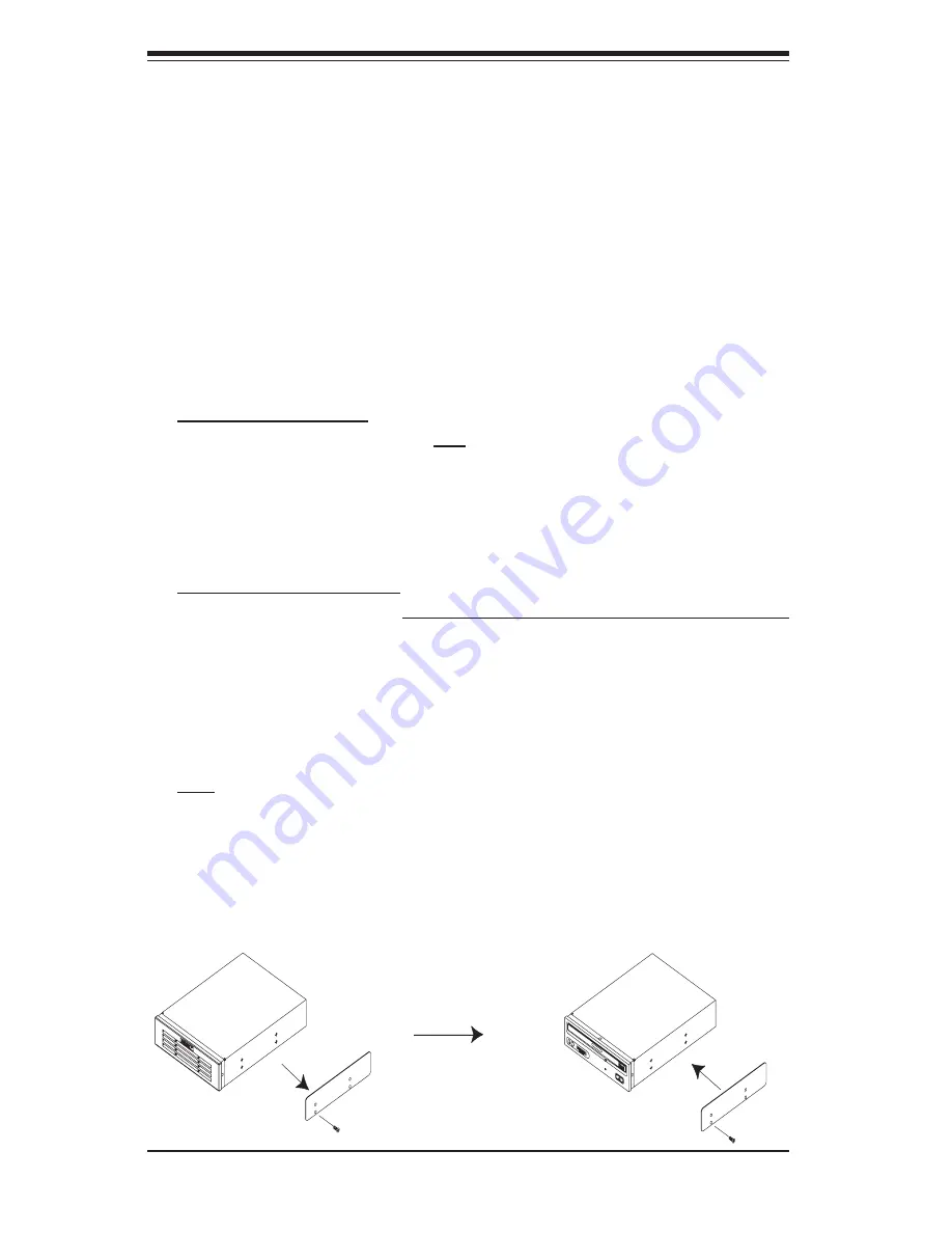
Adding a CD-ROM drive: remove the guide plate from right side of the empty
drive carrier and screw it into the right side of the CD-ROM drive using the holes
provided (see Figure 6-8). Then slide the CD-ROM into the bay and secure it to
the chassis with the drive carrier screws you fi rst removed. Attach the power and
data cables to the drive. Replace the top/left chassis cover before restoring power
to the system.
Adding an IDE or fl oppy drive: to add one of these drives, install it into one of the
removed empty drive carriers with the printed circuit board side toward the carrier
so that the drive's mounting holes align with those in the carrier. Secure the drive
to the carrier with four screws then slide the assembly into the bay and secure it to
the chassis with the drive carrier screws you fi rst removed. Attach the power and
data cables to the drive. Replace the top/left chassis cover before restoring power
to
the
system.
Note:
A red wire typically designates the location of pin 1. You should keep the
drive carriers inserted in any unused drive bays to reduce EMI and noise and to
facilitate the airfl ow inside the chassis.
Figure 6-8. Adding a Component Without a Drive Carrier
Summary of Contents for SuperWorkstation 5035G-T
Page 1: ...SUPER SUPERWORKSTATION 5035G T USER S MANUAL Revision 1 0...
Page 5: ...v Preface Notes...
Page 16: ...1 8 SUPERWORKSTATION 5035G T User s Manual Notes...
Page 19: ...Chapter 2 System Installation 2 3 Figure 2 1 Accessing the Inside of the 5035G T...
Page 24: ...3 4 SUPERWORKSTATION 5035G T User s Manual Notes...
Page 52: ...5 24 SUPERWORKSTATION 5035G T User s Manual Notes...
Page 64: ...6 12 SUPERWORKSTATION 5035G T Manual Notes...
Page 80: ...A 2 SUPERWORKSTATION 5035G T User s Manual Notes...
Page 104: ...C 18 SUPERWORKSTATION 5035G T User s Manual Notes...
Page 108: ...D 4 SUPERWORKSTATION 5035G T User s Manual Notes...


