Supero SuperServer 7046T-H6R User Manual Download Page 56

5-24

S

UPER

S

ERVER 7046T-H6R/7046T-H6RF User's Manual

Note: SD III Software Revision 1.0 can be downloaded from our Web Site at: ftp://ftp.

supermicro.com/utility/Supero_Doctor_III/. You can also download the SDIII User's 

Guide at: <http://www.supermicro.com/PRODUCT/Manuals/SDIII/UserGuide.pdf>. 

For Linux, we will recommend using Supero Doctor II.

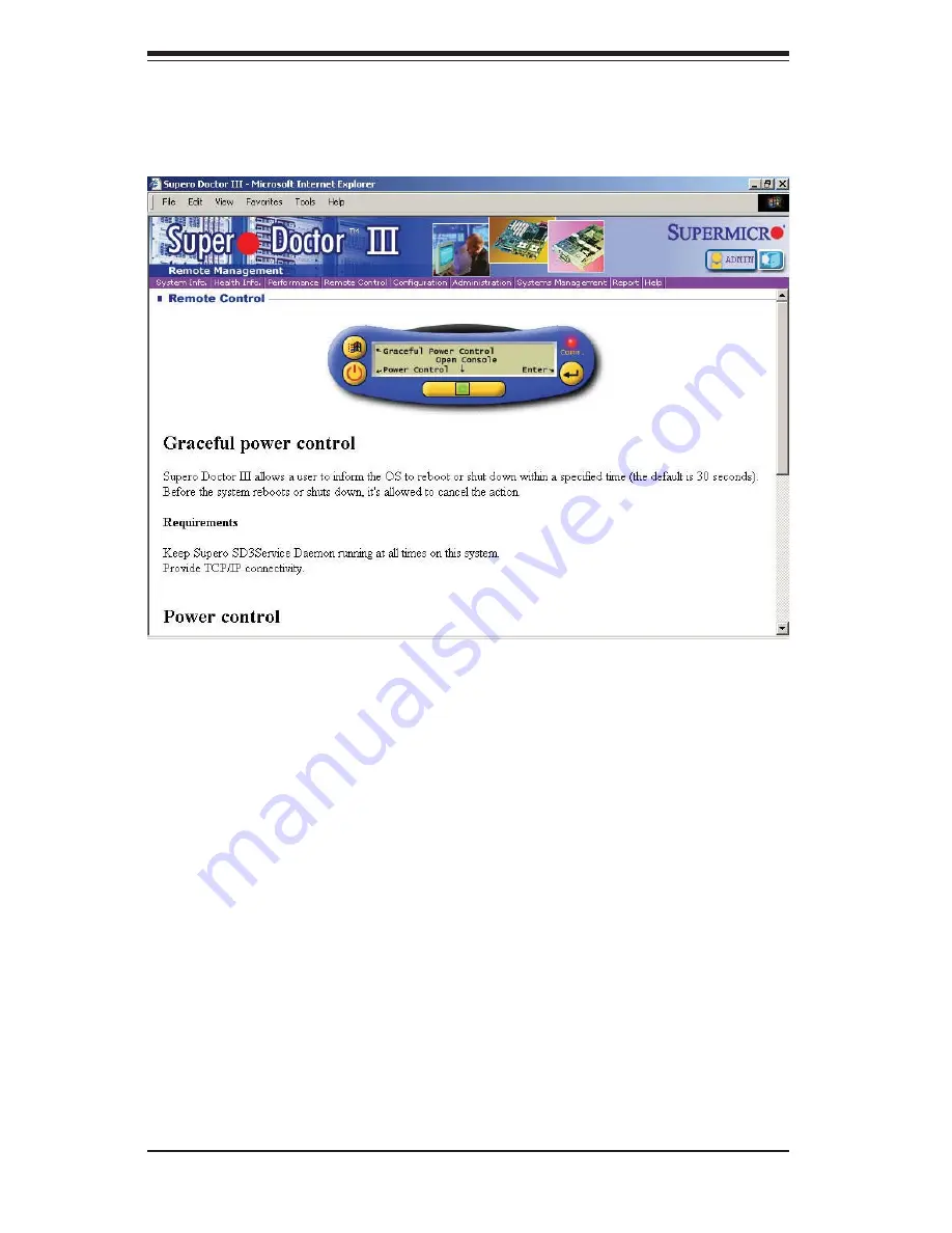
Supero Doctor III Interface Display Screen  (Remote Control)

Summary of Contents for SuperServer 7046T-H6R

Page 1: ...SUPERSERVER 7046T H6R SUPERSERVER 7046T H6RF SUPER USER S MANUAL 1 0...

Page 2: ...or the resolution of any such disputes Super Micro s total liability for all claims will not exceed the price paid for the hardware product FCC Statement This equipment has been tested and found to co...

Page 3: ...rverboard and the SC745TQ R800B chassis Chapter 2 Server Installation This chapter describes the steps necessary to install the SuperServer 7046T H6R 7046T H6RF into a rack and check out the server co...

Page 4: ...figuring the serverboard Chapter 6 Advanced Chassis Setup Refer to Chapter 6 for detailed information on the SC745TQ R800B server chassis You should follow the procedures given in this chapter when in...

Page 5: ...Notes Preface v...

Page 6: ...Installation 2 1 Overview 2 1 2 2 Unpacking the System 2 1 2 3 Preparing for Setup 2 1 Choosing a Setup Location 2 2 Rack Precautions 2 2 Server Precautions 2 2 Rack Mounting Considerations 2 3 Ambien...

Page 7: ...3 4 4 Operating Precautions 4 4 Chapter 5 Advanced Serverboard Setup 5 1 Handling the Serverboard 5 1 Precautions 5 1 Unpacking 5 2 5 2 Serverboard Installation 5 2 5 3 Connecting Cables 5 3 Connectin...

Page 8: ...Drives 6 6 SAS Backplane 6 7 Storage Module 6 9 Adding Drives to the Storage Module 6 10 Using a Mobile Rack 6 10 6 5 Power Supply 6 11 Power Supply Failure 6 11 Removing Replacing the Power Supply 6...

Page 9: ...on to the serverboard and chassis various hardware components have been included with the 7046T H6R 7046T H6RF as listed below Two passive heatsinks SNK P0038P Three 8 cm chassis fans FAN 0074L4 Two e...

Page 10: ...guration and requires modules of the same size and speed to be installed three at a time See Chapter 5 for details SAS An LSI2008 controller chip is integrated into the serverboard to provide an eight...

Page 11: ...T H6R 7046T H6RF provides you with system monitoring and control LEDs indicate system power HDD activity network activity system overheat and power supply failure A main power button and a system rese...

Page 12: ...4 Ports 5 6 Ports 9 10 USB PCI 33MHz SIO W83527HG LPC BUS 6 FRONT SPI WPCM450 U3H1 CPU 2 CPU 1 ESI x4 800 1066 1333 DDR3 1 4 1 3 1 2 1 1 1 5 1 6 0 5 0 6 800 1066 1333 0 4 0 3 0 2 0 1 DDR3 6Gb s SAS 0...

Page 13: ...per Micro Computer B V Het Sterrenbeeld 28 5215 ML s Hertogenbosch The Netherlands Tel 31 0 73 6400390 Fax 31 0 73 6416525 Email sales supermicro nl General Information support supermicro nl Technical...

Page 14: ...1 6 SUPERSERVER 7046T H6R 7046T H6RF User s Manual Notes...

Page 15: ...head to Section 2 5 2 2 Unpacking the System You should inspect the box the system was shipped in and note if it was damaged in any way If the server itself shows damage you should file a damage claim...

Page 16: ...In single rack installation stabilizers should be attached to the rack In multiple rack installations the racks should be coupled together Always make sure the rack is stable before extending a compon...

Page 17: ...quipment should be mounted into a rack so that the amount of airflow required for safe operation is not compromised Mechanical Loading Equipment should be mounted into a rack so that a hazardous condi...

Page 18: ...ctions that came with the rack unit you are using Identifying the Sections of the Rack Rails The optional rackmount kit includes two rack rail assemblies Each of these as semblies consist of three sec...

Page 19: ...hassis rail sections you just removed along the side of the chassis making sure the screw holes line up Note that these two rails are left right specific Screw the rail securely to the side of the cha...

Page 20: ...sition the fixed rack rail sliding rail guide assemblies at the desired location in the rack keeping the sliding rail guide facing the inside of the rack Screw the assembly securely to the rack using...

Page 21: ...se first keeping in mind that they are left right specific marked with L and R Then line up the rear of the chassis rails with the front of the rack rails Slide the chassis rails into the rack rails k...

Page 22: ...where it 4 says push then lift the latch to release the cover Lift the cover from the chassis to gain full access to the inside of the server 5 See Figure 2 5 Checking the Components and Setup You ma...

Page 23: ...s configuration your system may have one or 4 more drives already installed If you need to install SATA drives please refer to Chapter 6 Checking the Airflow Airflow is provided by four hot swap 8 cm...

Page 24: ...2 10 SUPERSERVER 7046T H6R 7046T H6RF User s Manual Figure 2 5 Accessing the Inside of the System Rack Configuration shown...

Page 25: ...status of the system and the activity and health of specific components 3 2 Control Panel Buttons There are two push buttons located on the front of the chassis a power on off button and a reset butt...

Page 26: ...ins what each LED indicates when illuminated and any corrective ac tion you may need to take 1 2 Power Indicates power is being supplied to the system s power supply This LED should normally be on whe...

Page 27: ...companied by an audible alarm A backup power supply module will take the load and keep the system running but the failed module will need to be replaced Refer to Chapter 6 for details on replacing the...

Page 28: ...3 4 SUPERSERVER 7046T H6R 7046T H6RF User s Manual Notes...

Page 29: ...down the operating system first and then unplug the power cords The unit has more than one power supply cord Disconnect both power supply cords before servicing to avoid electrical shock When working...

Page 30: ...esetting PTC Positive Tempera ture Coefficient fuses on the mainboard must be replaced by trained service technicians only The new fuse must be the same or equivalent as the one replaced Contact techn...

Page 31: ...ing measures are generally sufficient to neutralize this difference before contact is made to protect your equipment from ESD Use a grounded wrist strap designed to prevent static discharge Keep all c...

Page 32: ...f this practice is not strictly followed Figure 4 1 Installing the Onboard Battery LITHIUM BATTERY BATTERY HOLDER Please handle used batteries carefully Do not damage the battery in any way a damaged...

Page 33: ...ant to handle them very carefully see previous chapter To prevent the serverboard from bending keep one hand under the center of the board to support it when handling The following measures are genera...

Page 34: ...1 the top cover of the chassis then pull the cover off Make sure that the I O ports on the serverboard align properly with their 2 respective holes in the I O shield at the back of the chassis Careful...

Page 35: ...AS drive data cables SAS0 SAS7 Control Panel cable JF1 USB cable for front side access USB4 5 Important Make sure the the cables do not come into contact with the fans Connecting Power Cables The X8DT...

Page 36: ...us I O ports Figure 5 1 Control Panel Header Pins Figure 5 2 I O Ports NMI x Key Vcc Vcc Vcc Vcc Vcc Vcc Reset Button Power Button Ground x Key Power On LED HDD LED NIC1 LED NIC2 LED OH Fan Fail LED P...

Page 37: ...nd Heatsink When handling the processor package avoid placing direct pressure on the label area of the fan Notes Always connect the power cord last and always remove it before adding re moving or chan...

Page 38: ...the socket or its pins to avoid damaging the CPU or the socket With the CPU in the socket in 4 spect the four corners of the CPU to make sure that it sits level and is properly installed Once the CPU...

Page 39: ...damage the CPU Add the two remaining screws 5 then finish the installation by fully tightening all four screws Installing a CPU Heatsink Note see Chapter 6 for details on installing the air shroud Rem...

Page 40: ...s slot Pay attention to the notch 2 along the bottom of the module to avoid installing incorrectly see Figure 5 3 Gently press down on the DIMM module until it snaps into place in the slot 3 Repeat fo...

Page 41: ...A P1 DIMM3A 6 DIMMs P1 DIMM1A P1 DIMM1B P1 DIMM2A P1 DIMM2B P1 DIMM3A P1 DIMM3B Populating DIMMs for Optimal Performance For Two CPUs Installed CPU1 CPU2 Branch 0 Branch 1 Branch 3 Branch 0 Branch 1 B...

Page 42: ...Note Due to OS limitations some operating systems may not show more than 4 GB of memory Note Due to memory allocation to system devices the amount of memory that remains available for operational use...

Page 43: ...y JD1 JOH1 FAN2 SMBus JWD DP4 JF1 FAN3 SPI BIOS LED5 DP6 DP7 JPS1 RAID Key SATA SGPIO0 FAN7 FAN1 JPW2 JPW3 JPW1 Keyboard Mouse USB0 1 IPMI LAN COM1 VGA PHY LAN1 LAN2 JPL1 FAN8 BMC LAN Controller JI2C2...

Page 44: ...AN X8DTH F only JD1 Power LED Speaker Header JF1 Front Panel Connector JL1 Chassis Intrusion Header JOH1 Overheat LED Header JPI2 C Power Supply SMBbus I2 C Header JPW1 24 pin ATX Power Connector JPW2...

Page 45: ...12V 24 COM 12 3 3V Reset Button Pin Definitions JF1 Pin Definition 3 Reset 4 Ground Power Button Pin Definitions JF1 Pin Definition 1 Power Signal 2 Ground Secondary Power Connector JPW2 must also be...

Page 46: ...ED Pin Definitions JF1 Pin Definition 13 Vcc 14 HD Active NIC2 JLAN2 LED The LED connections for JLAN2 are on pins 9 and 10 of JF1 Attach an LED cable to display network activ ity See the table on the...

Page 47: ...port is above the keyboard port See the table on the right for pin definitions NMI Button The non maskable interrupt button header is located on pins 19 and 20 of JF1 Refer to the table on the right f...

Page 48: ...pin definitions Serial Port Pin Definitions Pin Definition Pin Definition 1 DCD 6 DSR 2 RXD 7 RTS 3 TXD 8 CTS 4 DTR 9 RI 5 Ground 10 NC Power LED Speaker On JD1 header pins 1 3 are for a power LED an...

Page 49: ...anagement Bus JPI2 C connector monitors the status of the power supply fan and system temperature See the table on the right for pin definitions Power I2C Connector Pin Definitions Pin Definition 1 Cl...

Page 50: ...2 1 3 2 1 CMOS Clear JBT1 is used to clear CMOS which will also clear any passwords Instead of pins this jumper consists of contact pads to prevent accidentally clearing the contents of CMOS To clear...

Page 51: ...ble on the right for jumper settings Watch Dog Enable Disable Jumper J21 controls the Watch Dog function Watch Dog is a system moni tor that can reboot the system when a software application hangs Jum...

Page 52: ...re to unplug the power cable before removing or adding any components See the table on the right for more details Onboard PWR LED Indicator LE1 LED Color Definition Off System Off PWR cable not connec...

Page 53: ...AS Activity LED is located at LED5 When LED5 is on SAS is active 5 12 SAS and SATA Ports SATA Ports There are no jumpers to configure the onboard SATA connectors See the table on the right for SATA po...

Page 54: ...ackaged with your motherboard Driver Tool Installation Display Screen Note Click the icons showing a hand writing on paper to view the readme files for each item Click the computer icons to the right...

Page 55: ...cial system information such as CPU temperature system voltages and fan status See the Figure below for a display of the Supero Doctor III interface Note The default User Name and Password for SuperDo...

Page 56: ...wnloaded from our Web Site at ftp ftp supermicro com utility Supero_Doctor_III You can also download the SDIII User s Guide at http www supermicro com PRODUCT Manuals SDIII UserGuide pdf For Linux we...

Page 57: ...rtant to handle them very carefully The following measures are generally sufficient to protect your equipment from static discharge Precautions Use a grounded wrist strap designed to prevent static di...

Page 58: ...6 2 SUPERSERVER 7046T H6R 7046T H6RF User s Manual Figure 6 1 Chassis Front View System Reset Main Power 5 25 Drive Bays 2 USB Ports 8 SATA Drive Bays behind locking bezel...

Page 59: ...over to the control panel side of the chassis The LEDs on the control panel inform you of system status see Figure 6 2 for details See Chapter 5 for details on JF1 Figure 6 2 Front Control Panel LEDs...

Page 60: ...orking Depress the locking tab on the failed fan on a chassis fan push the tab on 2 the side of the housing inward on the exhaust fan push down on the colored tab With the tab depressed pull the unit...

Page 61: ...Chapter 6 Advanced Chassis Setup 6 5 Figure 6 4 Removing the Air Shroud Figure 6 3 Removing a Chassis Fan...

Page 62: ...in order from bottom to top or from left to right if rackmounted A bezel covers the drive area but does not need to be re moved to access the drives simply swing open the bezel If you wish to remove t...

Page 63: ...ckplane with any metal objects and make sure no cables touch the backplane or obstruct the airflow holes Figure 6 5 Removing a SATA Drive Carrier SAS Backplane The SAS drives plug into a SAS backplane...

Page 64: ...o or four screws that secure the drive carrier 2 to the chassis one side only then push the entire empty drive carrier out from the back Adding a DVD ROM Drive Remove the guide plates one on each side...

Page 65: ...e chassis cover 1 Disconnect any cables from the storage module to any components in the 2 chassis Push the storage module release lever to unlock the storage module 3 Grasp the external edges of the...

Page 66: ...ge module which goes into the chassis Open the chassis cover 1 Locate the drive release tabs 2 Pull the first drive release tab and push the drive tray toward the front of the 3 chassis Repeat this fo...

Page 67: ...Fail LED will illuminate and remain on until the failed unit has been replaced Replacement units can be ordered directly from Supermicro see contact information in the Pref ace The hot swap capability...

Page 68: ...Installing a New Power Supply Replace the failed module with another power supply module must be the 1 exact same model Push the new power supply unit into the power bay until you hear a click 2 Finis...

Page 69: ...plays all the options that can be configured Grayed out options cannot be configured Options in blue can be configured by the user The right frame displays the key legend Above the key legend is an ar...

Page 70: ...ntial damages arising from a BIOS update If you have to update the BIOS do not shut down or reset the system while the BIOS is updating This is to avoid possible boot failure 7 2 Main Setup When you f...

Page 71: ...oard Speed This item displays the speed of the CPU detected by the BIOS Physical Count This item displays the number of processors installed in your system as detected by the BIOS Logical Count This i...

Page 72: ...s the bootup screen options to be modified between POST mes sages or the OEM logo Select Disabled to display the POST messages Select Enabled to display the OEM logo instead of the normal POST message...

Page 73: ...erride Restore on AC Power Loss Use this feature to set the power state after a power outage Select Power Off for the system power to remain off after a power loss Select Power On for the system power...

Page 74: ...lect Enable to enable Clock Spectrum support which will allow the BIOS to moni tor and attempt to reduce the level of Electromagnetic Interference caused by the components whenever needed The options...

Page 75: ...h will allow the processor to designate areas in the system memory where an application code can execute and where it cannot thus preventing a worm or a virus from flooding illegal codes to overwhelm...

Page 76: ...enabled the CPU will conditionally demote C6 or C7 re quests to C3 based on un core auto demote information The options are Disabled and Enabled ACPI T State Select Enabled to report Processor throttl...

Page 77: ...ard The options are Disabled and Enabled Memory Frequency This feature forces a DDR3 to run at a frequency other than what the system has detected The available options are Auto Force DDR 800 Force DD...

Page 78: ...lt is 006 Press or on your keyboard to change this value Inlet Temperature This is the temperature detected at the chassis inlet Each step is in 0 5o C increments The default is 070 Press or on your k...

Page 79: ...Select NUMA for SLES 11 for better CPU perfor mance on a SUSE Linux Enterprise Server 11 The options are Enabled Disabled and NUMA for SLES11 Intel I OAT The Intel I OAT I O Acceleration Technology si...

Page 80: ...settings The options are Intel and Adaptec SATA 2 Configuration This feature is available when the option IDE is selected for SATA 1 Selecting Enhanced will set SATA 2 to native SATA mode The options...

Page 81: ...detect the PIO mode Use this value if the IDE disk drive support cannot be determined Select 0 to allow the AMI BIOS to use PIO mode 0 It has a data transfer rate of 3 3 MB s Select 1 to allow the AMI...

Page 82: ...a data transfer rate of 133 MB s Select UDMA6 to allow the BIOS to use Ultra DMA mode 6 It has a data transfer rate of 133 MB s The options are Auto SWDMAn MWDMAn and UDMAn S M A R T For Hard disk dri...

Page 83: ...On first PCI E Slots 1 7 x8 This feature allows the user to Enable or Disable any of the PCI slots The options are Enable and Disable Onboard LAN Option ROM Select This feature allows the user to sel...

Page 84: ...erial port mode for Console Redirection The options are 115200 8 n 1 57600 8 n 1 38400 8 n 1 19200 8 n 1 and 9600 8 n 1 Flow Control This feature allows the user to set the flow control for Console Re...

Page 85: ...setting if you want the CPU overheat alarm includ ing the LED and the buzzer to be triggered as soon as the CPU temperature reaches the CPU overheat threshold as predefined by the CPU manufacturer The...

Page 86: ...Threshold or Temperature Tolerance has been assigned at the factory and is the baseline on which the motherboard takes action during different CPU temperature conditions Since CPUs can have different...

Page 87: ...DIMM 1 1V 1 5V 1 8V 3 3V 12V 5V 3 3 Vsb and VBAT XACPI Configuration Use this feature to configure Advanced Configuration and Power Interface ACPI power management settings for your system ACPI Aware...

Page 88: ...M jumper on the motherboard to enable TCG TPM 1 1 1 2 TPM support in order to improve data integrity and network security The options are No and Yes If this feature is set to Yes the following items w...

Page 89: ...oard Management Controller BMC manages the interface between system management software and platform hardware This section displays the BMC status codes XView BMC System Event Log This feature display...

Page 90: ...system If DHCP is selected the BIOS will search for a DHCP Dynamic Host Configuration Protocol server in the network that the system is attached to and request the next available IP address The optio...

Page 91: ...timed delay in minutes or seconds before a system powers down or resets after an operating system failure is detected The options are 5 Min 1 Min 30 Sec and 10 Sec XEvent Log Configuration View Event...

Page 92: ...to access the submenu and then type in a new Supervisor Password User Access Level Available when Supervisor Password is set as above The Options are Full Access View Only Limited and No Access Full...

Page 93: ...er it has been entered Password Check Select Setup to allow the system to check for a user or supervisor password when ever it enters into the BIOS Setup Select Always to allow the system to check for...

Page 94: ...allows the user to specify the boot sequence from available Removable Drives The settings are 1st boot device 2nd boot device and Disabled 1st Drive USB XXXXXXXXX 2nd Drive XCD DVD Drives This feature...

Page 95: ...lect this option to quit the BIOS Setup without making any permanent changes to the system configuration and reboot the computer Select Discard Changes and Exit from the Exit menu and press Enter Disc...

Page 96: ...46T H6RF User s Manual Load Fail Safe Defaults To set this feature select Load Fail Safe Defaults from the Exit menu and press Enter The Fail Safe settings are designed for maximum system stability bu...

Page 97: ...to proceed with the boot up procedure If a fatal error occurs you should consult with your system manufacturer for possible repairs These fatal errors are usually communicated through a series of aud...

Page 98: ...A 2 SUPERSERVER 7046T H6R 7046T H6RF User s Manual Notes...

Page 99: ...s supporting up to 96 GB of registered ECC or up to 24 GB of unbuffered ECC non ECC DDR3 1333 1066 800 SDRAM Note Interleaved memory requires memory must be installed four modules at a time See Sectio...

Page 100: ...onment Operating Temperature 10 to 35 C 32 to 95 F Non operating Temperature 40 to 70 C 40 to 158 F Operating Relative Humidity 20 to 95 non condensing Non operating Relative Humidity 5 to 95 non cond...

Page 101: ...B 3 Appendix B System Specifications Notes...

Page 102: ...to perform be reasonably expected to result in significant injury or loss of life or catastrophic property damage Accordingly Supermicro dis claims any and all liability and should buyer use or sell s...

Reviews: