


5-22
S
UPER
S
ERVER 6027R-73DARF User's Manual
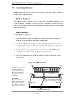
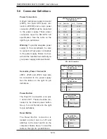
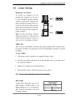
Standby Power Header
The +5V Standby Power header is lo-
cated at JSTBY1. See the table on the
right for pin defi nitions. (You must also
have a card with a Standby Power con-
nector and a cable to use this feature.)
Standby PWR
Pin Defi nitions
Pin# Defi nition
1
+5V Standby
2
Ground
3
Wake-up
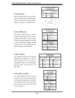
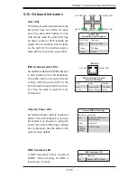
LAN3/LAN4 LED Indicators
The NIC (Network Interface Control-
ler) LED connections for LAN Ports 3
and 4 are located on pins 3/4 and 1/2
of JF2, respectively. Attach NIC LED
cables here to display network activi-
ties. Refer to the table on the right for
pin defi nitions.
Note
: The NIC LED connections for
LAN Ports 1/2 are located on JF1.
LAN Ports 3/4 LED Indicators (JF2)
Pin Defi nitions
Pin# Defi nition
Pin Defi nition
1
LAN4 Activity
2
LAN4 Link
3
LAN3 Activity
4
LAN3 Link
Summary of Contents for SUPERSERVER 6027R-73DARF
Page 1: ...SUPERSERVER 6027R 73DARF SUPER USER S MANUAL 1 0...
Page 5: ...Notes Preface v...
Page 14: ...1 6 SUPERSERVER 6027R 73DARF User s Manual Notes...
Page 22: ...2 8 SUPERSERVER 6027R 73DARF User s Manual Notes...
Page 26: ...SUPERSERVER 6027R 73DARF User s Manual 3 4 Notes...
Page 60: ...5 30 SUPERSERVER 6027R 73DARF User s Manual Notes...
Page 68: ...6 8 SUPERSERVER 6027R 73DARF User s Manual Notes...
Page 102: ...A 2 SUPERSERVER 6027R 73DARF User s Manual Notes...


