5-4
S
UPER
S
ERVER 1025C-M3 User's Manual
5-4 I/O
Ports
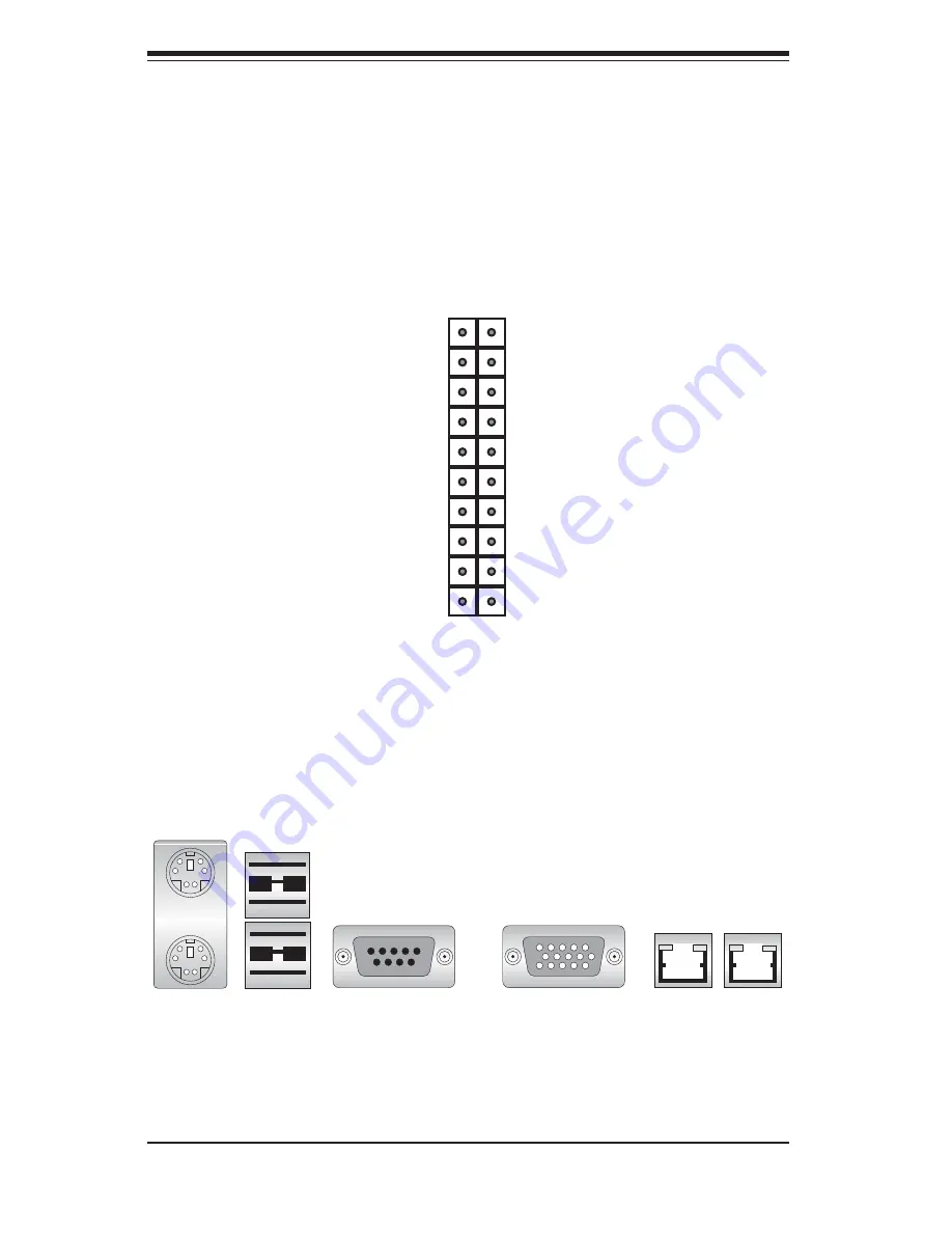
The I/O ports are color coded in conformance with the PC 99 specifi cation. See
Figure 5-2 below for the colors and locations of the various I/O ports.
Figure 5-1. Control Panel Header Pins
Note:
The COM2 port is a header on the serverboard, located near JWOR. COM2
should be connected to the COM port at the front of the chassis.
Mouse (Green)
LAN1 LAN2
Keyboard
(Purple)
COM1 Port (Turquoise)
VGA Port (Blue)
USB 0/1 Ports
Figure 5-2. I/O Ports
NMI
x (Key)
Vcc 5V Stby
Vcc 3V
Vcc 3V Stby
Vcc 3V Stby
Vcc 3V
Reserved
Reset (Button)
Power (Button)
Ground
x (Key)
Power On LED
IDE/SATA LED
NIC1 LED
NIC2 LED
OH/Fan Fail LED
Reserved
Ground
Ground
2 1
20 19
Connecting the Control Panel
JF1 contains header pins for various front control panel connectors. See Figure 5-1
for the pin locations of the various front control panel buttons and LED indicators. All
JF1 wires have been bundled into a single ribbon cable to simplify this connection.
Make sure the red wire plugs into pin 1 as marked on the board. The other end
connects to the Control Panel PCB board, located just behind the system status
LEDs on the chassis.
Summary of Contents for SuperServer 1025C-M3
Page 1: ...SUPER USER S MANUAL Revision 1 0 SUPERSERVER 1025C M3...
Page 5: ...v Preface Notes...
Page 10: ...SUPERSERVER 1025C M3 User s Manual x Notes...
Page 23: ...Chapter 2 Server Installation 2 7 Figure 2 4 Installing the Outer Rails to the Rack 2 3 3...
Page 28: ...2 12 SUPERSERVER 1025C M3 Manual Notes...
Page 32: ...3 4 SUPERSERVER 1025C M3 Manual Notes...
Page 69: ...Chapter 6 Advanced Chassis Setup 6 7 Figure 6 5 Installing a DVD ROM Drive...
Page 71: ...Chapter 6 Advanced Chassis Setup 6 9 Figure 6 6 Removing Replacing the Power Supply...
Page 72: ...6 10 SUPERSERVER 1025C M3 Manual Notes...
Page 100: ...A 6 SUPERSERVER 1025C M3 User s Manual Notes...
Page 106: ...B 6 SUPERSERVER 1025C M3 User s Manual Notes...
Page 110: ...C 4 SUPERSERVER 1025C M3 User s Manual Notes...


