Supermicro X6DA3-G2 User Manual Download Page 63

Chapter 4: Phoenix BIOS

4-7

4-4 Advanced 

Setup

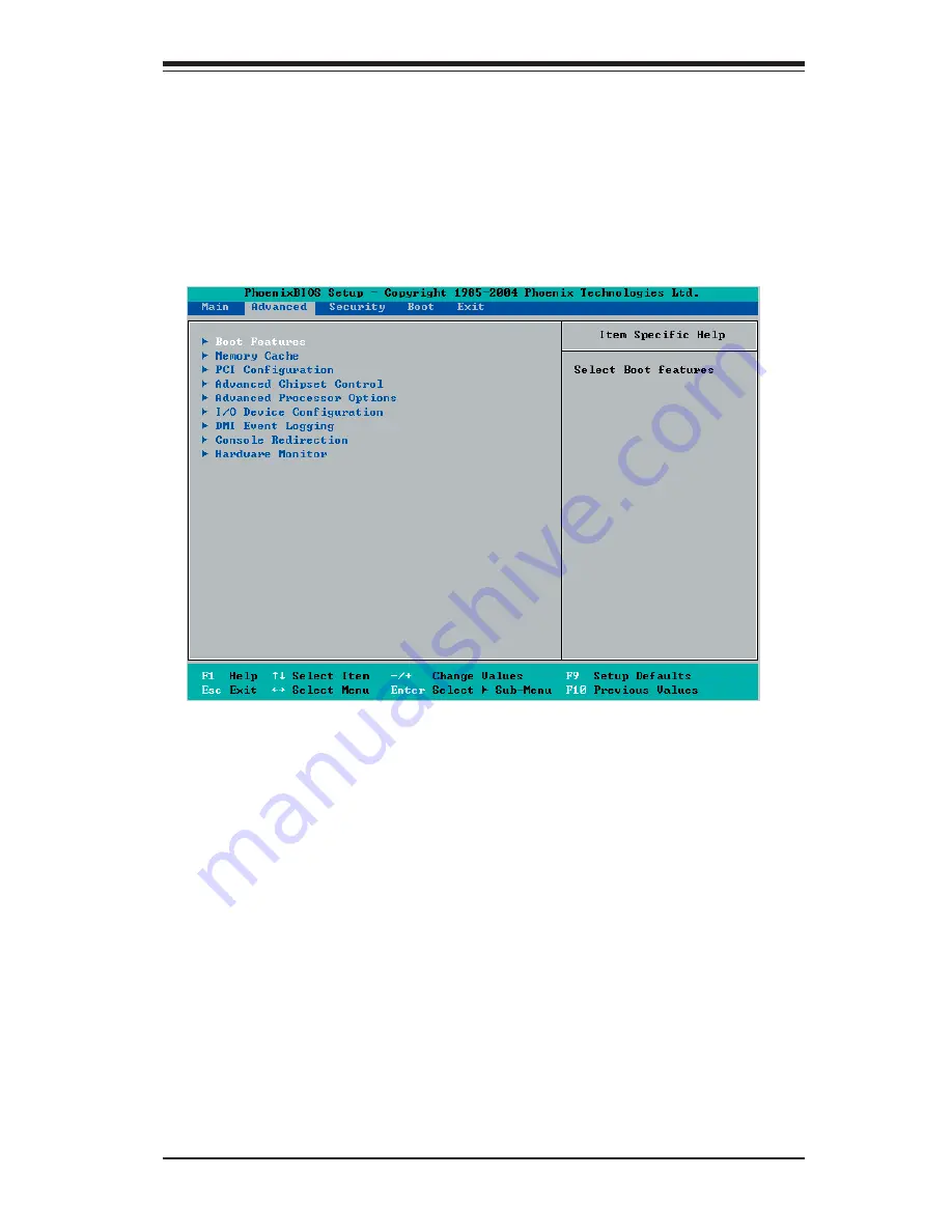
 Choose Advanced from the  Phoenix BIOS Setup Utility main menu with the arrow 

keys. You should see the following display.  An item with a triangle beside it has a 

sub menu  that can be accessed by highlighting the item and pressing <Enter>.  Op-

tions for PIR settings are displayed by highlighting the setting option by using the 

arrow keys and pressing <Enter>. All Advanced BIOS Setup options are described 

in this section. 

Boot Features

Access the submenu to make changes to the following settings.

Quick Boot Mode

If enabled, this feature will speed up the POST (Power On Self Test) routine by 

skipping certain tests after the computer is turned on. The settings are 

Enabled


and Disabled. If Disabled, the POST routine will run at the normal speed. 

Quiet Boot

When Enabled, the system will switch to the graphic mode and display OEM's logo 

during boot-up.   The system will  automatically switch to the text mode if an error 

occurs.  The settings are 

Enabled

 and Disabled. 

ACPI Mode

Use this setting to determine if you want to employ  ACPI (Advanced Confi guration 

and Power Interface) power management on your system.  The options are 

Yes


and No.

Summary of Contents for X6DA3-G2

Page 1: ... USER S MANUAL Revision 1 0 SUPER X6DA3 G2 X6DAi G2 ...

Page 2: ...BILITY TO USE THIS PRODUCT OR DOCUMENTATION EVEN IF ADVISED OF THE POSSIBILITY OF SUCH DAMAGES IN PARTICULAR THE VENDOR SHALL NOT HAVE LIABILITY FOR ANY HARDWARE SOFTWARE OR DATA STORED OR USED WITH THE PRODUCT INCLUDING THE COSTS OF REPAIRING REPLACING INTEGRATING INSTALLING OR RECOVERING SUCH HARDWARE SOFTWARE OR DATA Any disputes arising between manufacturer and customer shall be governed by th...

Page 3: ...ides hardware installation instructions Read this chapter when installing the processor memory modules and other hardware components into the system If you encounter any problems see Chapter 3 which describes troubleshooting procedures for the video the memory and the system setup stored in CMOS Chapter 4 includes an introduction to BIOS and provides detailed information on running the CMOS Setup ...

Page 4: ...ealth Monitoring 1 10 1 5 ACPI Features 1 11 1 6 Power Supply 1 12 1 7 Super I O 1 12 Chapter 2 Installation 2 1 Static Sensitive Devices 2 1 Precautions 2 1 Unpacking 2 1 2 2 Xeon Processor and Heatsink Installation 2 2 2 3 Installing DIMMs 2 6 2 4 Control Panel Connectors I O Ports 2 7 A Back Panel Connectors IO Ports 2 7 B Front Control Panel 2 8 C Front Control Panel Pin Definitions 2 9 NMI But...

Page 5: ...n Fail LED 2 20 SMB 2 20 SMB PWR Connector 2 21 SAS SMB PWR Connector 2 21 AC 97 Audio Audio Enable 2 22 CD Connectors 2 22 Audio Enable Disable 2 22 2 6 Jumper Settings 2 23 Explanation of Jumpers 2 23 GLAN Enable Disable 2 23 CMOS Clear 2 24 SAS Control Enable 2 24 Watch Dog Enable 2 25 3rd Power Supply Power Fault Detect 2 26 Power Force On Enable 2 26 2 8 Onboard Indicators 2 27 GLAN LEDs 2 27...

Page 6: ...ystem s Setup Configuration 3 2 3 2 Technical Support Procedures 3 2 3 3 Frequently Asked Questions 3 3 3 4 Returning Merchandise for Service 3 4 Chapter 4 BIOS 4 1 Introduction 4 1 4 2 Running Setup 4 2 4 3 Main BIOS Setup 4 2 4 4 Advanced Setup 4 7 4 5 Security Setup 4 19 4 6 Boot Setup 4 21 4 7 Exit 4 22 Appendices Appendix A BIOS POST Error Messages A 1 Appendix B BIOS POST Codes B 1 Appendix C...

Page 7: ...ormance Check that the following items have all been included with your motherboard If anything listed here is damaged or missing contact your retailer All included with Retail Box One 1 Supermicro Mainboard One 1 ribbon cable for IDE devices CBL 036 One 1 floppy ribbon cable CBL 022 Two 2 SAS cables CBL 097 For the X6DA3 G2 only One 1 I O backpanel shield CSE PT 53 One 1 Supermicro CD containing d...

Page 8: ...ress SuperMicro Computer B V Het Sterrenbeeld 28 5215 ML s Hertogenbosch The Netherlands Tel 31 0 73 6400390 Fax 31 0 73 6416525 Email sales supermicro nl General Information support supermicro nl Technical Support rma supermicro nl Customer Support Asia Pacific Address SuperMicro Taiwan 4F No 232 1 Liancheng Road Chung Ho 235 Taipei County Taiwan R O C Tel 886 2 8226 3990 Fax 886 2 8226 3991 Web S...

Page 9: ...Chapter 1 Introduction 1 3 Figure 1 1 X6DA3 G2 X6DAi G2 Image ...

Page 10: ...33MHz PCI X 100MHz Slot1 PCI X 100MHz ZCR 82546GB SAS CTRL JS1 JS2 JS3 I2 C JSM1 JSM2 SAS 4 7 SAS 0 3 JSLED1 J P 8 AIC 9410W Figure 1 2 X6DA3 G2 X6DAi G2 Motherboard Layout not drawn to scale Notes 1 Jumpers not indicated are for test purposes only 2 See Chapter 2 for detailed information on jumpers I O ports and JF1 front panel connections 3 indicates the location of Pin 1 4 The graphics shown in...

Page 11: ... J3 IDE2 J4 IDE1 2 Hard Disk Drive Connectors IPMI J20 IPMI 2 0 Socket KB MOUSE J9 Keyboard Mouse Keylock JK1 Keylock Connection LAN JLAN1 G bit Ethernet Ports Line_In Line_Out Mic Audio Line_In Line_Out JC2 Microphone JC1 OH LED JOH1 Overheat LED Printer J23 Parallel Printer Port PWR LED SPKR JD1 PWR LED Pins1 3 Speaker Pins 4 7 PWR Fault JP12 Power Fault Connector PWR Alarm Reset JAR PWR Fail Al...

Page 12: ...etting before install ing a supported OS Note visit www Intel com for CPU support and driver updates Memory Eight 240 pin DIMM sockets supporting up to 16 GB Registered ECC DDRII 400 PC3200 SDRAM Memory must be populated in pairs Chipset Intel E7525 North Bridge ICH5R South Bridge PHX PCI Controller Hub Expansion Slots One PCI Express x16 slot Slot 6 One PCI Express x4 Slot 4 using x16 physical sl...

Page 13: ... WOL Headers PWR On mode for AC power recovery Internal external modem ring on STR Suspend to RAM Onboard I O Adaptec AIC 9410W 8 port Serial Attached SCSI Controller SAS X6DA3 G2 only RAID 0 1 One IPMI 2 0 Socket One dual port Intel 82546GB Gigabit Ethernet controller 2 EIDE Ultra DMA 100 bus master interfaces 1 floppy port interface up to 2 88 MB 1 EPP ECP Parallel Port PS 2 mouse and PS 2 keyboa...

Page 14: ... B PCI EXP A 1PCI X SLOT 1PCI X PCI X BUS 133M HZ G Bit LAN SLOT J 13 PCI X BUS 100M HZ J 14 1 PCI EXP SLOT J 17 PC I EXP B C X16 J 15 1 PCI EXP SLOT IDE PRI SEC X8 X4 X4 0 1 SATA SATA LPCBUS USB USB PORTS 0 1 2 3 BM C CON FWH LPC I O PARALLEL M S FDD SER 1 SER 2 KB 4 DDRII 4 DDRII DDRII 400 SAS 9410W PC I BUS 32 BIT PCI 32 BIT SLOT AC 97 J 19 1PCI X SLOT J 12 H W M ONITOR 5 6 7 J L AN1 ATTLA DIMM...

Page 15: ...00 per channel The E7525 also supports the new PCI Express high speed serial I O interface for superior I O bandwidth The MCH provides configurable x16 PCI Express interfaces which may alternatively be configured as two independent x8 PCI Express interfaces These interfaces support connection of the MCH to a variety of other bridges that are compliant with the PCI Express Interface Specification Rev ...

Page 16: ...g This section describes the PC health monitoring features of the X6DA3 G2 X6DAi G2 All have an onboard System Hardware Monitor chip that supports PC health monitoring Onboard Voltage Monitors for the CPU Cores Chipset Voltage 3 3V 5V 12V 12V 3 3V Standby and 5V Standby An onboard voltage monitor will scan these voltages continuously Once a voltage becomes unstable a warning is given or an error m...

Page 17: ...tandard way to integrate power management features throughout a PC system including its hardware operating system and application software This enables the system to automatically turn on and off peripherals such as CD ROMs network cards hard disk drives and printers This also includes consumer devices connected to the PC such as VCRs TVs telephones and stereos In addition to enabling operating sy...

Page 18: ... also required for adequate power supply to the system Also your power supply must supply 1 5A for the Ethernet ports It is strongly recommended that you use a high quality power supply that meets ATX power supply Specification 2 02 or above It must also be SSI compliant info at http www ssiforum org Additionally in areas where noisy power transmission is present you may choose to install a line fil...

Page 19: ...hanced Parallel Port EPP or Extended Capabilities Port ECP The Super I O provides functions that comply with ACPI Advanced Configuration and Power Interface which includes support of legacy and ACPI power manage ment through an SMI or SCI function pin It also features auto power management to reduce power consumption The IRQs DMAs and I O space resources of the Super I O can flexibly adjust to meet ...

Page 20: ...1 14 X6DA3 G2 X6DAi G2 User s Manual Notes ...

Page 21: ...o not touch its components peripheral chips memory modules or gold contacts When handling chips or modules avoid touching their pins Put the motherboard and peripherals back into their antistatic bags when not in use For grounding purposes make sure your computer chassis provides excellent conductivity between the power supply the case the mounting fasteners and the motherboard Use only the correc...

Page 22: ... not place the motherboard on a conductive surface which can damage the BIOS battery and prevent the system from booting up Socket lever CPU Installation 1 Lift the lever on the CPU socket lift the lever completely as shown on the picture on the right otherwise you will damage the CPU socket when power is applied Install CPU1 first CPU Retention Plates are pre in stalled Pictures shown on right are...

Page 23: ...o not fully tighten the screws to avoid pos sible damage to the CPU 4 Finish the installation by fully tightening all four screws Screw 1 Screw 2 Pin 1 2 Insert the CPU in the socket mak ing sure that pin 1 of the CPU aligns with pin 1 of the socket both corners are marked with a triangle When using only one CPU install it into CPU socket 1 socket 2 is automatically disabled if only one CPU is use...

Page 24: ...rews from the motherboard in the sequence as show in the picture on the right 2 Hold the heatsink in the way as show in the picture on the right and gently wriggle the heatsink to loosen it from the CPU Do not use excessive force when wriggling the heatsink 3 Once the CPU is loosened from the heatsink remove the heatsink from the CPU socket 4 Clean the surface of the CPU and the heatsink to get ri...

Page 25: ... the metal standoffs click in or are screwed in tightly Then use a screwdriver to secure the motherboard onto the motherboard tray Note some components are very close to the mounting holes Please take precautionary measures to prevent damage done to these components when you install the motherboard to the chassis Lever Processor installed Triangle Triangle Empty socket Warning Make sure you lift t...

Page 26: ...prevent inserting the DIMM module incorrectly 3 Gently press down on the DIMM module until it snaps into place in the slot Repeat for all modules see step 1 above Memory Support The X6DA3 G2 X6DAi G2 supports up 16GB to dual channel ECC Registered DDR II 400 SDRAM This motherboard supports Interleaved memory Populating DIMM 1A DIMM 1B and or DIMM 2A DIMM 2B with a pair or pairs of memory modules t...

Page 27: ...colors and locations of the various I O ports A Back Panel Connectors IO Ports Figure 2 3 Back Panel I O Port Locations and Definitions II JLAN1 Back Panel Connectors 1 Keyboard Purple 2 PS 2 Mouse Green 3 Back Panel USB Port 0 4 Back Panel USB Port 1 5 Back Panel USB Port 2 6 Back Panel USB Port 3 7 COM Port 1 Turquoise 8 Parallel Port Printer 9 COM Port 2 Turquoise 10 Gigabit LAN 2 11 Gigabit LAN...

Page 28: ...esigned specifi cally for use with Supermicro server chassis See Figure 2 4 for the descriptions of the various control panel buttons and LED indicators Refer to the following section for descriptions and pin definitions Figure 2 4 JF1 Header Pins Power Button OH Fan Fail LED 1 NIC1 LED Reset Button 2 HDD LED Power LED Reset PWR Vcc Vcc Vcc Vcc Ground Ground 19 20 Vcc X Ground NMI X Vcc PWR Fail LED...

Page 29: ...Bank 2 Bank 2 Bank 3 Bank 3 Bank 4 Bank 4 ATX PWR JPF JPAC Audio Enable SI O PCI EXP x16 J 2 7 CD1 CD2 GLAN CTRL Battery SMBus SATA1 Fan3 JPS1 J 2 0 JWD J K 1 Keylock Fan8 Clear CMOS FAN1 8 pin PWR JC2 JC1 JWOL JL1 J 3 P JAR JOH1 JP15 JP12 P X H GLAN USB4 5JD3 FAN2 WOR Slot6 Slot5 ICH5R PCI 33MHz Slot4 PCI EXP x4 Slot3 Slot2 PCI X 133MHz PCI X 100MHz Slot1 PCI X 100MHz ZCR 82546GB SAS CTRL I2 C SA...

Page 30: ...SAS CTRL I2 C SAS 4 7 SAS 0 3 JSLED1 AIC 9410W Power Button OH Fan Fail LED 1 NIC1 LED Reset Button 2 HDD LED Power LED Reset PWR Vcc Vcc Vcc Vcc Ground Ground 19 20 Vcc X Ground NMI X Vcc PWR Fail LED NIC2 LED NIC1 NIC2 LED Indicators The NIC Network Interface Control ler LED connection for GLAN port1 is located on pins 11 and 12 of JF1 and the LED connection for GLAN Port2 is on Pins 9 and 10 At...

Page 31: ...MHz PCI X 100MHz Slot1 PCI X 100MHz ZCR 82546GB SAS CTRL I2 C SAS 4 7 SAS 0 3 JSLED1 AIC 9410W Power Button OH Fan Fail LED 1 NIC1 LED Reset Button 2 HDD LED Power LED Reset PWR Vcc Vcc Vcc Vcc Ground Ground 19 20 Vcc X Ground NMI X Vcc PWR Fail LED NIC2 LED Overheat Fan Fail LED OH Connect an LED to the OH Fan Fail connection on pins 7 and 8 of JF1 to provide advanced warning of chassis overheati...

Page 32: ...S 4 7 SAS 0 3 JSLED1 AIC 9410W Power Button OH Fan Fail LED 1 NIC1 LED Reset Button 2 HDD LED Power LED Reset PWR Vcc Vcc Vcc Vcc Ground Ground 19 20 Vcc X Ground NMI X Vcc PWR Fail LED NIC2 LED Power Button The Power Button connection is located on pins 1 and 2 of JF1 Momentarily contacting both pins will power on off the system This button can also be con figured to function as a suspend button w...

Page 33: ...5V 10 12V 23 5V 11 12V 24 COM 12 3 3V Required Connection Required Connection 12V 4 pin Power Con nector Pin Definitions Pins Definition 1 and 2 Ground 3 and 4 12V 12V 8 pin Power Con nector Pin Definitions Pins Definition 1 through 4 Ground 5 through 8 12V K B Mouse DIMM 4A DIMM 4B DIMM 3A DIMM 3B DIMM 2A DIMM 2B DIMM 1A DIMM 1B SPKR GLAN Enable E7525 NorthBridge South Bridge IPMI 2 0 BIOS IDE 1 IDE ...

Page 34: ...Floppy Fan4 USB6 7 SATA0 FP CTRL FAN7 PWRSMB CPU1 CPU2 J D 1 USB 0 1 2 3 JLAN1 COM2 COM1 Parrallel Port Fan6 Fan5 4 pin PWR Bank 1 Bank 1 Bank 2 Bank 2 Bank 3 Bank 3 Bank 4 Bank 4 ATX PWR JPF JPAC Audio Enable SI O PCI EXP x16 J 2 7 CD1 CD2 GLAN CTRL Battery SMBus SATA1 Fan3 JPS1 J 2 0 JWD J K 1 Keylock Fan8 Clear CMOS FAN1 8 pin PWR JC2 JC1 JWOL JL1 J 3 P JAR JOH1 JP15 JP12 P X H GLAN USB4 5JD3 F...

Page 35: ...actions made on the keyboard effectively locking it Keylock Pin Definitions Pin Definition 1 Ground 2 Keylock R N K B Mouse DIMM 4A DIMM 4B DIMM 3A DIMM 3B DIMM 2A DIMM 2B DIMM 1A DIMM 1B SPKR GLAN Enable E7525 NorthBridge South Bridge IPMI 2 0 BIOS IDE 1 IDE 2 Floppy Fan4 USB6 7 SATA0 FP CTRL FAN7 PWRSMB CPU1 CPU2 J D 1 USB 0 1 2 3 JLAN1 COM2 COM1 Parrallel Port Fan6 Fan5 4 pin PWR Bank 1 Bank 1 Ba...

Page 36: ...D 8 CTS 4 DTR 9 RI 5 Ground K B Mouse DIMM 4A DIMM 4B DIMM 3A DIMM 3B DIMM 2A DIMM 2B DIMM 1A DIMM 1B SPKR GLAN Enable E7525 NorthBridge South Bridge IPMI 2 0 BIOS IDE 1 IDE 2 Floppy Fan4 USB6 7 SATA0 FP CTRL FAN7 PWRSMB CPU1 CPU2 J D 1 USB 0 1 2 3 JLAN1 COM2 COM1 Parrallel Port Fan6 Fan5 4 pin PWR Bank 1 Bank 1 Bank 2 Bank 2 Bank 3 Bank 3 Bank 4 Bank 4 ATX PWR JPF JPAC Audio Enable SI O PCI EXP x...

Page 37: ...in Definitions JWOL Pin Definition 1 5V Standby 2 Ground 3 Wake up K B Mouse DIMM 4A DIMM 4B DIMM 3A DIMM 3B DIMM 2A DIMM 2B DIMM 1A DIMM 1B SPKR GLAN Enable E7525 NorthBridge South Bridge IPMI 2 0 BIOS IDE 1 IDE 2 Floppy Fan4 USB6 7 SATA0 FP CTRL FAN7 PWRSMB CPU1 CPU2 J D 1 USB 0 1 2 3 JLAN1 COM2 COM1 Parrallel Port Fan6 Fan5 4 pin PWR Bank 1 Bank 1 Bank 2 Bank 2 Bank 3 Bank 3 Bank 4 Bank 4 ATX PWR...

Page 38: ... P X H GLAN USB4 5JD3 FAN2 WOR Slot6 Slot5 ICH5R PCI 33MHz Slot4 PCI EXP x4 Slot3 Slot2 PCI X 133MHz PCI X 100MHz Slot1 PCI X 100MHz ZCR 82546GB SAS CTRL I2 C SAS 4 7 SAS 0 3 JSLED1 AIC 9410W Power LED Speaker On the JD1 header pins 1 3 are for a power LED and pins 4 7 are for the speaker See the table on the right for speaker pin definitions Note The speaker connector pins are for use with an ext...

Page 39: ...il LED Pin Definitions Pin Definition 1 PWR 1 Fail 2 PWR 2 Fail 3 PWR 3 Fail 4 Signal Alarm Reset Alarm Reset Pin Setting Definition Pin 1 Ground Pin 2 5V K B Mouse DIMM 4A DIMM 4B DIMM 3A DIMM 3B DIMM 2A DIMM 2B DIMM 1A DIMM 1B SPKR GLAN Enable E7525 NorthBridge South Bridge IPMI 2 0 BIOS IDE 1 IDE 2 Floppy Fan4 USB6 7 SATA0 FP CTRL FAN7 PWRSMB CPU1 CPU2 J D 1 USB 0 1 2 3 JLAN1 COM2 COM1 Parrallel P...

Page 40: ...g Fan Fail K B Mouse DIMM 4A DIMM 4B DIMM 3A DIMM 3B DIMM 2A DIMM 2B DIMM 1A DIMM 1B SPKR GLAN Enable E7525 NorthBridge South Bridge IPMI 2 0 BIOS IDE 1 IDE 2 Floppy Fan4 USB6 7 SATA0 FP CTRL FAN7 PWRSMB CPU1 CPU2 J D 1 USB 0 1 2 3 JLAN1 COM2 COM1 Parrallel Port Fan6 Fan5 4 pin PWR Bank 1 Bank 1 Bank 2 Bank 2 Bank 3 Bank 3 Bank 4 Bank 4 ATX PWR JPF JPAC Audio Enable SI O PCI EXP x16 J 2 7 CD1 CD2 ...

Page 41: ... Mouse DIMM 4A DIMM 4B DIMM 3A DIMM 3B DIMM 2A DIMM 2B DIMM 1A DIMM 1B SPKR GLAN Enable E7525 NorthBridge South Bridge IPMI 2 0 BIOS IDE 1 IDE 2 Floppy Fan4 USB6 7 SATA0 FP CTRL FAN7 PWRSMB CPU1 CPU2 J D 1 USB 0 1 2 3 JLAN1 COM2 COM1 Parrallel Port Fan6 Fan5 4 pin PWR Bank 1 Bank 1 Bank 2 Bank 2 Bank 3 Bank 3 Bank 4 Bank 4 ATX PWR JPF JPAC Audio Enable SI O PCI EXP x16 J 2 7 CD1 CD2 GLAN CTRL Batt...

Page 42: ...onnectors CD1 CD2 are located next to the GLAN Controller See the tables on the right for pin definitions CD1 Pin Definition Pin Definition 1 Left 2 Ground 3 Ground 4 Right CD2 Pin Definition Pin Definition 1 Right 2 Ground 3 Left 4 Ground K B Mouse DIMM 4A DIMM 4B DIMM 3A DIMM 3B DIMM 2A DIMM 2B DIMM 1A DIMM 1B SPKR GLAN Enable E7525 NorthBridge South Bridge IPMI 2 0 BIOS IDE 1 IDE 2 Floppy Fan4 USB6 ...

Page 43: ...r jumper settings The default setting is enabled GLAN Enable Pin Definition 1 2 Enabled default 2 3 Disabled K B Mouse DIMM 4A DIMM 4B DIMM 3A DIMM 3B DIMM 2A DIMM 2B DIMM 1A DIMM 1B SPKR GLAN Enable E7525 NorthBridge South Bridge IPMI 2 0 BIOS IDE 1 IDE 2 Floppy Fan4 USB6 7 SATA0 FP CTRL FAN7 PWRSMB CPU1 CPU2 J D 1 USB 0 1 2 3 JLAN1 COM2 COM1 Parrallel Port Fan6 Fan5 4 pin PWR Bank 1 Bank 1 Bank 2...

Page 44: ...lt setting is enabled SAS Controller Enable Jumper Settings Jumper Setting Definition Pins 1 2 Enabled default Pins 2 3 Disabled K B Mouse DIMM 4A DIMM 4B DIMM 3A DIMM 3B DIMM 2A DIMM 2B DIMM 1A DIMM 1B SPKR GLAN Enable E7525 NorthBridge South Bridge IPMI 2 0 BIOS IDE 1 IDE 2 Floppy Fan4 USB6 7 SATA0 FP CTRL FAN7 PWRSMB CPU1 CPU2 J D 1 USB 0 1 2 3 JLAN1 COM2 COM1 Parrallel Port Fan6 Fan5 4 pin PWR ...

Page 45: ...ng Definition Pins 1 2 Reset default Pins 2 3 NMI Open Disabled K B Mouse DIMM 4A DIMM 4B DIMM 3A DIMM 3B DIMM 2A DIMM 2B DIMM 1A DIMM 1B SPKR GLAN Enable E7525 NorthBridge South Bridge IPMI 2 0 BIOS IDE 1 IDE 2 Floppy Fan4 USB6 7 SATA0 FP CTRL FAN7 PWRSMB CPU1 CPU2 J D 1 USB 0 1 2 3 JLAN1 COM2 COM1 Parrallel Port Fan6 Fan5 4 pin PWR Bank 1 Bank 1 Bank 2 Bank 2 Bank 3 Bank 3 Bank 4 Bank 4 ATX PWR J...

Page 46: ...e this the default setting with J3P to prevent false alarms 3rd PWR Supply PWR Fault Jumper Settings Jumper Setting Definition Closed Enabled Open Disabled Default K B Mouse DIMM 4A DIMM 4B DIMM 3A DIMM 3B DIMM 2A DIMM 2B DIMM 1A DIMM 1B SPKR GLAN Enable E7525 NorthBridge South Bridge IPMI 2 0 BIOS IDE 1 IDE 2 Floppy Fan4 USB6 7 SATA0 FP CTRL FAN7 PWRSMB CPU1 CPU2 J D 1 USB 0 1 2 3 JLAN1 COM2 COM1 ...

Page 47: ...0 Act 6 SAS4 Act 2 SAS1 Act 7 SAS5 Act 3 SAS2 Act 8 SAS6 Act 4 SAS3 Act 9 SAS7 Act 5 SAS Common 10 NC GLAN Power Indicator LED Color Definition Off No Connection Green 10 100 Mbps Amber 1 Gbps K B Mouse DIMM 4A DIMM 4B DIMM 3A DIMM 3B DIMM 2A DIMM 2B DIMM 1A DIMM 1B SPKR GLAN Enable E7525 NorthBridge South Bridge IPMI 2 0 BIOS IDE 1 IDE 2 Floppy Fan4 USB6 7 SATA0 FP CTRL FAN7 PWRSMB CPU1 CPU2 J D 1...

Page 48: ... D 1 USB 0 1 2 3 JLAN1 COM2 COM1 Parrallel Port Fan6 Fan5 4 pin PWR Bank 1 Bank 1 Bank 2 Bank 2 Bank 3 Bank 3 Bank 4 Bank 4 ATX PWR JPF JPAC Audio Enable SI O PCI EXP x16 J 2 7 CD1 CD2 GLAN CTRL Battery SMBus SATA1 Fan3 JPS1 J 2 0 JWD J K 1 Keylock Fan8 Clear CMOS FAN1 8 pin PWR JC2 JC1 JWOL JL1 J 3 P JAR JOH1 JP15 JP12 P X H GLAN USB4 5JD3 FAN2 WOR Slot6 Slot5 ICH5R PCI 33MHz Slot4 PCI EXP x4 Slo...

Page 49: ... Bit 0 4 Error 5 Data Bit 1 6 Init 7 Data Bit 2 8 SLCT IN 9 Data Bit 3 10 GND 11 Data Bit 4 12 GND 13 Data Bit 5 14 GND 15 Data Bit 6 16 GND 17 Data Bit 7 18 GND 19 ACK 20 GND 21 BUSY 22 Write Data 23 PE 24 Write Gate 25 SLCT 26 NC K B Mouse DIMM 4A DIMM 4B DIMM 3A DIMM 3B DIMM 2A DIMM 2B DIMM 1A DIMM 1B SPKR GLAN Enable E7525 NorthBridge South Bridge IPMI 2 0 BIOS IDE 1 IDE 2 Floppy Fan4 USB6 7 S...

Page 50: ... Socket on the motherboard Refer to the layout below for the IPMI Socket location K B Mouse DIMM 4A DIMM 4B DIMM 3A DIMM 3B DIMM 2A DIMM 2B DIMM 1A DIMM 1B SPKR GLAN Enable E7525 NorthBridge South Bridge IPMI 2 0 BIOS IDE 1 IDE 2 Floppy Fan4 USB6 7 SATA0 FP CTRL FAN7 PWRSMB CPU1 CPU2 J D 1 USB 0 1 2 3 JLAN1 COM2 COM1 Parrallel Port Fan6 Fan5 4 pin PWR Bank 1 Bank 1 Bank 2 Bank 2 Bank 3 Bank 3 Bank...

Page 51: ...CS16 33 Addr1 34 Ground 35 Addr0 36 Addr2 37 Chip Select 0 38 Chip Select 1 39 Activity 40 Ground K B Mouse DIMM 4A DIMM 4B DIMM 3A DIMM 3B DIMM 2A DIMM 2B DIMM 1A DIMM 1B SPKR GLAN Enable E7525 NorthBridge South Bridge IPMI 2 0 BIOS IDE 1 IDE 2 Floppy Fan4 USB6 7 SATA0 FP CTRL FAN7 PWRSMB CPU1 CPU2 J D 1 USB 0 1 2 3 JLAN1 COM2 COM1 Parrallel Port Fan6 Fan5 4 pin PWR Bank 1 Bank 1 Bank 2 Bank 2 Ba...

Page 52: ... B18 Ground K B Mouse DIMM 4A DIMM 4B DIMM 3A DIMM 3B DIMM 2A DIMM 2B DIMM 1A DIMM 1B SPKR GLAN Enable E7525 NorthBridge South Bridge IPMI 2 0 BIOS IDE 1 IDE 2 Floppy Fan4 USB6 7 SATA0 FP CTRL FAN7 PWRSMB CPU1 CPU2 J D 1 USB 0 1 2 3 JLAN1 COM2 COM1 Parrallel Port Fan6 Fan5 4 pin PWR Bank 1 Bank 1 Bank 2 Bank 2 Bank 3 Bank 3 Bank 4 Bank 4 ATX PWR JPF JPAC Audio Enable SI O PCI EXP x16 J 2 7 CD1 CD2...

Page 53: ...chassis speaker and the power LED to the motherboard Check all jumper settings as well 5 Use the correct type of onboard CMOS battery as recommended by the Manu facturer Do not install the onboard battery upside down to avoid possible explosion No Power 1 Make sure no short circuits exist between the motherboard and the chassis 2 Verify that all jumpers are set to their default positions 3 Check t...

Page 54: ... and so on see Section 2 3 Losing the System s Setup Configuration 1 Make sure that you are using a high quality power supply A poor quality power supply may cause the system to lose the CMOS setup information Refer to Section 1 6 for details on recommended power supplies 2 The battery on your motherboard may be old Check to verify that it still sup plies 3VDC If it does not replace it with a new o...

Page 55: ...The X6DA3 G2 X6DAi G2 has eight 240 pin DIMM slots that support reg istered ECC DDR2 400 PC3200 SDRAM modules It is strongly recommended that you do not mix memory modules of different speeds and sizes Please refer to Chapter 2 for instructions on memory support Question How do I update my BIOS Answer It is recommended that you do not upgrade your BIOS if you are experi encing no problems with you...

Page 56: ...g to the manufacturer the RMA number should be prominently displayed on the outside of the shipping carton and mailed prepaid or hand carried Shipping and handling charges will be applied for all orders that must be mailed when service is complete This warranty only covers normal consumer use and does not cover damages in curred in shipping or from failure due to the alternation misuse abuse or im...

Page 57: ... turned off a back up battery provides power to the CMOS Memory in RTC Logic enabling it to retain system parameters Each time the computer is powered on the computer is configured with the values stored in the CMOS Memory by the system BIOS which gains control at boot up How To Change the Configuration Data The CMOS information that determines the system parameters may be changed by entering the BI...

Page 58: ... turning the video on or 2 When the message shown below appears briefly at the bottom of the screen during the POST Power On Self Test press the Delete key to activate the main Setup menu Press the Delete key to enter Setup 4 3 Main BIOS Setup All main Setup options are described in this section The main BIOS Setup screen is displayed below Use the Up Down arrow keys to move between the different s...

Page 59: ...nter the correct data Press the Enter key to save the data BIOS Date This field displays the date when this version of BIOS was built Legacy Diskette A This setting allows the user to set the type of floppy disk drive installed as diskette A The options are Disabled 360Kb 5 25 in 1 2MB 5 25 in 720Kb 3 5 in 1 44 1 25MB 3 5 in and 2 88MB 3 5 in Parallel ATA This setting allows the user to enable or di...

Page 60: ...e Non RAID driver Native Mode Operation Select the native mode for ATA The options are Parallel ATA Serial ATA Both and Auto IDE Channel 0 Master Slave IDE Channel 1 Master Slave IDE Channel 2 Master IDE Channel 3 Master These settings allow the user to set the parameters of IDE Channel 0 Master Slave IDE Channel 1 Master Slave IDE Channel 2 Master IDE Channel 3 Master slots Hit Enter to activate ...

Page 61: ... Cylinders This item indicates the status of Cylinders Headers This item indicates the number of headers Sectors This item displays the number of sectors Maximum Capacity This item displays the maximum storage capacity of the system LBA Format The following items will be displayed by the BIOS Total Sectors This item displays the number of total sectors available in the LBA Format Maximum Capacity ...

Page 62: ...a to be transferred on both rising and falling edges of the clock doubling data throughput for any given clock speed The options are Disabled Mode 0 Mode 1 Mode 2 Mode 3 Mode 4 and Mode 5 Please refer to the table below for detailed infomation Selects Ultra DM A Mode The options are Disabled Mode 0 Mode 1 Mode 2 Mode 3 Mode 4 and Mod5 Ultra DMA Mode Cycle Time Nanoseconds Maximum Transfer Rate MB ...

Page 63: ...the submenu to make changes to the following settings Quick Boot Mode If enabled this feature will speed up the POST Power On Self Test routine by skipping certain tests after the computer is turned on The settings are Enabled and Disabled If Disabled the POST routine will run at the normal speed Quiet Boot When Enabled the system will switch to the graphic mode and display OEM s logo during boot ...

Page 64: ... received by your modem The options are On and Off Keyboard on Now Function This option allows you to select how the system may be resumed from the S3 S5 state The options are Space by pressing the sapce bar Password by entering a password and Disabled Set Power On Password Enter up to 5 digits of letters and numbers to set a Power On Password to allow the user to power on the system Power Loss Co...

Page 65: ...d up CPU operations Select Uncached to disable this function Select Write Through to allow data to be cached into the system memory and into L1 L2 L3 cache area of the CPU at the same time Select Write Protect to prevent data from being cached into the system memory area of Block 0 512K Select Write Back to allow CPU to write data back directly from the L1 L2 L3 cache inside the CPU without writin...

Page 66: ...user can achieve better graphic effects when using a Linux graphic driver that requires the write combining configuration with 4GB or more memory The options are Enabled and Disabled PCI Configuration Access the submenu to make changes to the following settings for PCI devices Onboard GLAN Gigabit LAN OPROM Configure Enabling this option provides the capability to boot from GLAN The options are Enabl...

Page 67: ...Hz PCI X 66 MHz PCI X 100 MHz and PCI X 133 MHz PCI X 100MHz ZCR Slot 1 PCI X 100MHz Slot 2 PCI X 133MHz Slot 3 PCI E X4 Slot 4 PCI 33MHz Slot 5 PCI E X16 Slot 6 Access the submenu for each of the settings above to make changes to the following Option ROM Scan When enabled this setting will initialize the device expansion ROM The options are Enabled and Disabled Enable Master This setting allows y...

Page 68: ...ces will overlap with the physical memory if 4GB of memory or above is installed on the motherboard When this occurs enable this function to reallocate the overlapped physical memory to a location above 4GB to resolve the memory overlapping situation Delayed Transaction Discard Select Disabled to set the ESB P2P Bridge Secondary Discard Timer to 32 micro seconds for the PCI 32 bus Select Enabled t...

Page 69: ...of Machine Checking and allow the CPU to detect and report hardware machine errors via a set of model specific registers MSRs The options are Disabled or Enabled C1 Enhanced Mode Available when supported by the CPU Set to Enabled to enable Enhanced Halt State to lower CPU voltage frequency to prevent overheat The options are Enabled and Disabled Note please refer to Intel s web site for detailed in...

Page 70: ...1 GV3 are disabled If set to C States only the processor power will be controlled through CPU power states in the APCI setting I O Device Configuration Access the submenu to make changes to the following settings KBC Clock input This setting allows you to set the clock frequency for the Keyboard Clock The options are 6MHz 8MHz and 12 MHz Onboard COM1 This setting allows you to assign control of ser...

Page 71: ... for the parallel port The options are 378 278 and 3BC Interrupt This setting allows you to select the IRQ interrupt request for the parallel port The options are IRQ5 and IRQ7 Mode This setting allows you to specify the parallel port mode The options are Output Bi directional ECP and EPP DMA Channel This setting allows you to specify the DMA channel mode The options are DMA1 and DMA3 Floppy Disk ...

Page 72: ... 115 2K Console Type This setting allows you to choose from the available options to select the console type for console redirection The options are VT100 VT100 8bit PC ANSI 7bit PC ANSI VT100 VT UTF8 Flow Control This setting allows you to choose from the available options to select the flow control for console redirection The options are None XON XOFF and CTS RTS Console Connection This feature a...

Page 73: ...orming you of the event log capacity View DMI Event Log Highlight this item and press Enter to view the contents of the event log Event Logging This setting allows you to Enable or Disable event logging ECC Event Logging This setting allows you to Enable or Disable ECC event logging Mark DMI Events as Read Highlight this item and press Enter to mark the DMI events as read Clear All DMI Event Logs ...

Page 74: ...ed will be controlled by Pulse Width Modulation PWM Select 3 pin if your chassis came with 3 pin fan headers Select 4 pin if your chassis came with 4 pin fan headers Select Workstation if your system is used as a Workstation Select Server if your system is used as a Server Select Disable to disable the fan speed control function to allow the onboard fans to run at the full speed 12V at all the tim...

Page 75: ...password has been entered for the system Clear means such a password has not been used and Set means a supervisor password has been entered for the system User Password Is This displays whether a user password has been entered for the system Clear means such a password has not been used and Set means a user password has been entered for the system Set Supervisor Password When the item Set Supervis...

Page 76: ...lows access to the system at boot up Fixed Disk Boot Sector This setting may offer some protection against viruses when set to Write Protect which protects the boot sector on the hard drive from having a virus written to it The other option is Normal Password on Boot This setting allows you to require a password to be entered when the system boots up The options are Enabled password required and D...

Page 77: ...em Specific Help window All Boot BIOS settings are described in this section Removable Devices Highlight and press Enter to expand the field See details on how to change the order and specs of devices in the Item Specific Help window CD ROM Drive See details on how to change the order and specs of the CD ROM drive in the Item Specific Help window Hard Drive Highlight and press Enter to expand the field...

Page 78: ...lity Exit Discarding Changes Highlight this item and hit Enter to exit the BIOS Setup utility without saving any changes you may have made Load Setup Defaults Highlight this item and hit Enter to load the default settings for all items in the BIOS Setup These are the safest settings to use Discard Changes Highlight this item and hit Enter to discard cancel any changes you made You will remain in t...

Page 79: ...Failed Keyboard controller failed test May require replacing keyboard controller Keyboard locked Unlock key switch Unlock the system to proceed Monitor type does not match CMOS Run SETUP Monitor type not correctly identified in Setup Shadow Ram Failed at offset nnnn Shadow RAM failed at offset nnnn of the 64k block at which the error was detected System RAM Failed at offset nnnn System RAM failed a...

Page 80: ...vious POST did not complete successfully POST loads default values and offers to run Setup If the failure was caused by incorrect values and they are not corrected the next boot will likely fail On systems with control of wait states improper Setup settings can also terminate POST and cause this error on the next boot Run Setup and verify that the waitstate configuration is correct This error is cl...

Page 81: ...s Software NMI Failed ServerBIOS2 test error Cannot generate software NMI Non Maskable Interrupt Fail Safe Timer NMI Failed ServerBIOS2 test error Fail Safe Timer takes too long device Address Conflict Address conflict for specified device Allocation Error for device Run ISA or EISA Configuration Utility to resolve resource conflict for the specified device CD ROM Drive CD ROM Drive identified Entering S...

Page 82: ...ully tested nnnn kB System RAM Passed Where nnnn is the amount of system RAM in kilobytes successfully tested One or more I2O Block Storage Devices were excluded from the Setup Boot Menu There was not enough room in the IPL table to display all installed I2O block stor age devices Operating system not found Operating system cannot be located on either drive A or drive C Enter Setup and see if fixed...

Page 83: ...rd Write down and follow the information shown on the screen Press F2 to enter Setup Optional message displayed during POST Can be turned off in Setup PS 2 Mouse PS 2 mouse identified Run the I2O Configuration Utility One or more unclaimed block storage devices have the Configuration Request bit set in the LCT Run an I2O Configuration Utility e g the SAC utility System BIOS shadowed System BIOS copied...

Page 84: ...A 6 X6DA3 G2 X6DAi G2 User s Manual Notes ...

Page 85: ...ort 80h The following is a list of codes that may be written to port 80h Appendix B BIOS POST Codes POST Code Description 02h Verify Real Mode 03h Disable Non Maskable Interrupt NMI 04h Get CPU type 06h Initialize system hardware 07h Disable shadow and execute code from the ROM 08h Initialize chipset with initial POST values 09h Set IN POST flag 0Ah Initialize CPU registers 0Bh Enable CPU cache 0Ch...

Page 86: ...h Shadow system BIOS ROM 3Ah Auto size cache 3Ch Advanced configuration of chipset registers 3Dh Load alternate registers with CMOS values 41h Initialize extended memory for RomPilot 42h Initialize interrupt vectors 45h POST device initialization 46h 2 1 2 3 Check ROM copyright notice 47h Initialize I20 support 48h Check video configuration against CMOS 49h Initialize PCI bus and devices 4Ah Initial...

Page 87: ...nt 80h Disable onboard Super I O ports and IRQs 81h Late POST device initialization 82h Detect and install external RS232 ports 83h Configure non MCD IDE controllers 84h Detect and install external parallel ports 85h Initialize PC compatible PnP ISA devices 86h Re initialize onboard I O ports 87h Configure Motherboard Configurable Devices optional 88h Initialize BIOS Data Area 89h Enable Non Maskable...

Page 88: ...e QuietBoot optional B6h Check password optional B7h Initialize ACPI BIOS B9h Prepare Boot BAh Initialize SMBIOS BBh Initialize PnP Option ROMs BCh Clear parity checkers BDh Display MultiBoot menu BEh Clear screen optional BFh Check virus and backup reminders C0h Try to boot with INT 19 C1h Initialize POST Error Manager PEM C2h Initialize error logging C3h Initialize error display function C4h Ini...

Page 89: ...size EEh Shadow Boot Block EFh System memory test F0h Initialize interrupt vectors F1h Initialize Run Time Clock F2h Initialize video F3h Initialize System Management Manager F4h Output one beep F5h Clear Huge Segment F6h Boot to Mini DOS F7h Boot to Full DOS If the BIOS detects error 2C 2E or 30 base 512K RAM error it displays an addi tional word bitmap xxxx indicating the address line or bits th...

Page 90: ...B 6 X6DA3 G2 X6DAi G2 User s Manual Notes ...

Page 91: ... unpar alleled data storage expansion and inter connectivity capability Note The on board SAS Controller supports both SATA and SAS RAID configuration however mixing and matching SATA and SAS in the configuration is not recommended Using the Adaptec RAID Configuration Utility ARC Note Please also refer to the following sections for SATA RAID Configuration The onboard SAS Controller is enabled by defau...

Page 92: ...ct this option use the arrow keys and the enter key to select Managing Arrays from the main menu as shown above A Using the Array Configuration Utility The Array Configuration Utility enables you to create manage and delete arrays from the controller s BIOS add and delete spare drives and initialize drives Dur ing the system startup press Ctrl and A simultaneously to display the main menu ...

Page 93: ...t to prevent the loss of data Deleted arrays cannot be restored To delete an existing array 1 Turn on your computer and press Ctrl A when prompted to access the Adaptec RAID Configuration Utility 2 From the Adaptec RAID Configuration Utility main menu select Array Configu ration Utility 3 From the Array Configuration Utility menu select Manage Arrays 4 Select the array you wish to delete and press Del...

Page 94: ... 1 Turn on your computer and press Ctrl A when prompted to access the Adaptec RAID Configuration Utility 2 From the Adaptec RAID Configuration Utility menu select Array Configuration Utility Main Menu 3 From the Array Configuration Utility menu select Create Array 4 Select the disks for the new array and press Insert as the screen shown below Note To deselect any disk highlight the disk and press Dele...

Page 95: ...rties menu as shown in the screen below select an array type and press Enter Note that only the available array types RAID 0 and RAID1 are displayed on the screen RAID 0 or RAID 1 requires two drives 2 Under the item Arrays Label type in an label and press Enter Note The label shall not be more than 15 characters 3 For RAID 0 select the desired stripe size Note Available stripe sizes are 16 32 and...

Page 96: ... When migrating from single volume to RAID 0 migrating from a larger drive to a smaller drive is allowed However the destination drive must be at least half the capacity of the source drive 6 Adaptec does not recommend that you migrate or build an array on Windows dynamic disks volumes as it will result in data loss Warning Do not interrupt the creation of a RAID 0 using the Migrate option If you ...

Page 97: ...reen displays 2 From the Select Drive to Create Boot Unit list select the drive you wish to Configure Boot Unit and press Insert The Drive you have selected appears in the right window as shown in the screen below 3 Select the disk drive you wish to configure as a bootable drive from the Se lected Drives List in the right window and press Enter The next screen appears ...

Page 98: ...lect the Boot Unit list in the right window select the bootable drive you wish to delete and press Delete The following screen appears 3 When the screen shown above appears select Delete and press Enter 4 Enter Y to delete a bootable array when the following message is displayed Do you want to delete the Bootable uUit Yes No Then the bootable array will be deleted ...

Page 99: ...rive 4 Use the up and down arrow keys to highlight and select the disk you want to designate as a Hotspare and press Insert and then press Enter 5 Press yes when the following prompt is displayed Do you want to create spare Yes No The spare you have selected will appear in the Select Drive Menu To Delete a HotSpare Drive 4 From the List of Assigned HotSpare Drives in the right window select the ho...

Page 100: ...a disk overwrites the partition table on the disk and makes any data on the disk inaccessible If the drive is used in an array you may not be able to use the array again Do not initialize a disk that is part of a boot array To determine which disks are associated with a particular array Please refer to Viewing Array Properties To initialize drives 1 Turn on your computer and press Ctrl A when prom...

Page 101: ...een below select Initialize Drives and press Enter 4 From the Select drives for initialization list on the left screen select the disk you wish to initialize and press Insert The drive you ve selected will appear on the Selected Drives list as show below ...

Page 102: ...re selected and press En ter 6 When the following message appears make sure that you have selected the correct drive for initialization and press Y to initialize the drive or press N to quit Warning Initialization will configure the drive s as simple volume disk s Do you want to continue Yes No ...

Page 103: ...rform a Rebuild to get the array to Optimal status For a criti cal array Rebuild operation the optimal drive is the source drive Note 2 If no spare array exists and a hard disk drive fails you need to create a spare before you can rebuild an array To Rebuild an array 1 From the Main Menu select Manage Arrays as shown in the screen below From the List of Arrays select the array you want to Rebuild ...

Page 104: ...nables you to configure SAS disk drive settings To access the SAS utilities 1 Turn on your computer and press Ctrl A when prompted to access the Adaptec RAID Configuration Utility as shown in the screen below 2 Use the arrow keys to select SerialSelect Utility and press Enter to access the Controller Configuration submenu ...

Page 105: ... press F6 Note The default setting for each item is listed below Runtime BIOS Enabled BBS Support Device POST Banner Display Enabled CTRL A Message Display Enabled Physical Drives Display during POST Enabled 6 Press Esc to return to the previous menu and to exit the utility To Set Controller Configuration 3 Select Controller Configuration and press Enter to access the submen as shown below ...

Page 106: ...ialSelect Utility and press Enter to access the Physical Configuration submenu as shown below 3 Select Physical Configuration and press Enter to access SAS Device Con figuration submenu as shown below 4 Use the arrow keys to select an item Then press Enter and the arrow keys to configure the item selected 5 To load default settings press F6 6 Press Esc to return to the previous menu and to exit the ut...

Page 107: ...enu select Disk Utilities from the screen as shown above and press Enter 3 When the submenu appears select the desired disk and press Enter The following options are available 1 Format Disk Simulates a low level format of the hard drive by writing zeros to the entire disk Note Serial ATA drives are low level formatted at the factory and do not need to be low level formatted again Caution Formattin...

Page 108: ...figurations press ESC to exit The following screen will appear 2 Press Yes to exit the Utility For more information regarding Adaptec RAID Utility please refer to Adaptec s User s Guide in the CD included in your shipping package You can also download a copy of Adaptec User s Guide from our web site at www supermicro com ...

Page 109: ...CD g Press the F6 key when the message Press F6 if you need to install a third party SCSI or RAID driver displays h When the Windows OS Setup screen appears press S to specify additional device s i Insert the driver diskette Adaptec Embedded Serial ATA Raid Controller Driver into Drive A and press the Enter key j Choose Adaptec Embedded Host Serial ATA Raid Controller from the list indi cated in t...

Page 110: ... optional The bottom icon with a CD on it allows you to view the entire contents of the CD Please refer to the Adaptec User s Guide for the installation of Adaptec s Serial ATA RAID Controller Driver Adaptec s User s Guide is included in the CD You can also download a copy of the user s guide from our web site C 3 Installing Other Software Programs and Drivers A Installing Drivers other than Adapt...

Page 111: ...ent is called SD III Client The Supero Doctor III program included on the CDROM that came with your motherboard allows you to moni tor the environment and operations of your system Supero Doctor III displays crucial system information such as CPU temperature system voltages and fan status See the Figure below for a display of the Supero Doctor III interface Supero Doctor III Interface Display Scre...

Page 112: ...aded from our Web site at ftp ftp supermicro com utility Supero_Doctor_III You can also download SDIII User s Guide at http www supermicro com PROD UCT Manuals SDIII UserGuide pdf For Linux we will still recommend Supero Doctor II 2 For detailed information on Adaptec s SCSI SATA RAID Utility please refer to the CDs that came with your motherboard ...

Reviews: