


Chapter 2: Installation
2-7
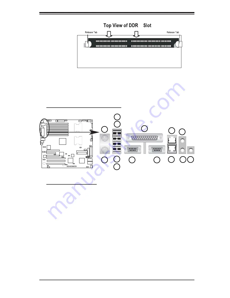
To Remove:
Use your thumbs
to gently push
the release tabs
near both ends of
the module. This
should release it
from the slot.
2-4 Control Panel Connectors/IO Ports
The I/O ports are color coded in conformance with the PC 99 specifi cation. See
Figure 2-3 below for the colors and locations of the various I/O ports.
A. Back Panel Connectors/IO Ports
Figure 2-3. Back Panel I/O Port Locations and Defi nitions
II
JLAN1
Back Panel Connectors
1. Keyboard (Purple)
2. PS/2 Mouse (Green)
3. Back Panel USB Port 0
4. Back Panel USB Port 1
5. Back Panel USB Port 2
6. Back Panel USB Port 3
7. COM Port 1 (Turquoise)
8. Parallel Port (Printer)
9. COM Port 2 (Turquoise)
10. Gigabit LAN 2
11. Gigabit LAN 1
12. Line-In
13. Line-Out
14. Mic.
(*See Section 2-5 for details.)
1
2
3
4
5
6
7
8
9
10
11
12
13
14
Summary of Contents for X6DA3-G2
Page 1: ... USER S MANUAL Revision 1 0 SUPER X6DA3 G2 X6DAi G2 ...
Page 9: ...Chapter 1 Introduction 1 3 Figure 1 1 X6DA3 G2 X6DAi G2 Image ...
Page 20: ...1 14 X6DA3 G2 X6DAi G2 User s Manual Notes ...
Page 84: ...A 6 X6DA3 G2 X6DAi G2 User s Manual Notes ...


