1-5
Safety Information and Technical Specifications
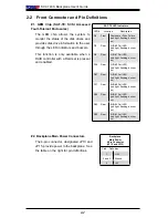
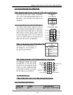
You must use the 4-pin power connectors:
JP13, JP10 to provide adequate power to the
Backplane. See the table on the right for pin
definitions.
Pins #
1
2 & 3
4
Definition
+12 V
Ground
+5V
Backplane Main
PWR
4-pin Connector
(J10)
A-3. Front Connector Pin Definitions
#1/#2. Backplane Main Power Connectors (JP10, JP13 ) Pin Definitions
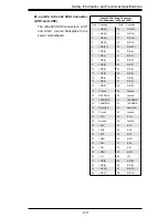
The Activity LED Header, located at JP26 on
the front panel, transmits signals to indicate the
activity status of each SAS slot. For the Activity
LED Header to work properly, please connect
an 8-pin LED cable to Pin 1 to Pin 4 and Pin 6
to Pin 9 of JP26 as shown on the right. See the
table in Section A-5 for pin definitions.
1
NC
2
Act In#3
Act In#2
NC
NC
Empty
3
4
5
6
7
8
9
NC
NC
Act In#1
Act In#0
(*Note 1:
"NC"=No Connection,
Note 2: Connect a 4-pin LED cable to
Pin1-Pin 4 of JP26 only.)
JP26
Pin# Pin#
SAS Activity LED
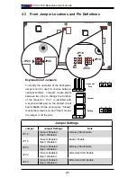
The Sideband Headers are located
at JP52/JP51 on the front panel.
For SAS-II to work properly, please
connect an 8-pin Sideband cables
to JP52/JP51 as shown on the right.
See the table for pin definitions.
6
5
8
7
10 9
Controller ID
Backplane ID
GND
SB1
No Connection
4
3
Reset
1
2
SB6
SB5
Backplane
Addressing
SB0
SB2
GND
SB4
SDA
SB3
SCL
SB7
Sideband Pin Definitions (JP51)
No Connection
#3. Activity LED Header: JP26 Pin Definitions
#8. AMI MG9072 Chip
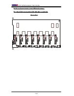
(*Note: Please refer to Pg. 1-7 for SAS Connectors/Locations
Act In#4
Act In#5
Act In#6
Act In#7
Act In#0
Act In#2
Act In#3
Act In#1
Ground
1
NC
2
Act I
n#3
Act I
n#2
NC
NC
Empt
y
3
4
5
6
7
8
9
NC
NC
Act I
n#1
Act I
n#0
(*N
ote
1:
"N
C"=
No
Con
nec
tio
n,
N
ote
2:
Con
nec
t a
4-p
in
LED
ca
ble
to
Pin1
-Pin
4 o
f J
P26
onl
y.)
JP26
Pin#
Pin#
SAS Act
ivi
ty
LED
Empty
#6/#7. Sideband Headers: JP52 (Sideband#2)/JP51 (Sideband#1)
There are four I
2
C Connectors on
the Backplane. See the table on
the right for pin definitions.
I2C
Pin Definitions
Pin# Definition
1
Data
2
Ground
3
Clock
4
No Connection
#4/#5. I
2
C Connectors: JP45 (I
2
C#2)/JP44 (I
2
C#1)
A-4
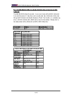
Front Panel LED Indicator:
Front LED
State
Specification
D3 (Front)
On
Overheat or Drive Failure
Summary of Contents for SC745S2-800VB
Page 4: ...SC745 Chassis Manual iv Notes ...
Page 14: ...SC745 Chassis Manual 1 4 Notes ...
Page 50: ...Chassis Manual 5 26 Notes ...
Page 62: ...Chassis Manual 6 12 Notes ...
Page 64: ...Appendicies 2 Notes ...
Page 68: ...Chassis Manual A 4 Notes ...
Page 70: ...Chassis Manual B 2 Notes ...
Page 71: ...Rev 1 0 SCA 743S2 Backplane USER S GUIDE JP13 JP10 ...
Page 74: ...iv SCA 743S Backplane User s Guide Notes ...
Page 76: ...1 2 SCA 743S Backplane User s Guide Notes ...
Page 84: ...2 8 SCA 743S Backplane User s Guide Notes ...
Page 95: ...1 0 SUPER USER S GUIDE Mobile Rack CSE M35S CSE M35T1 ...


