background image

6-9

Chapter 6: Rack Installation

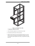
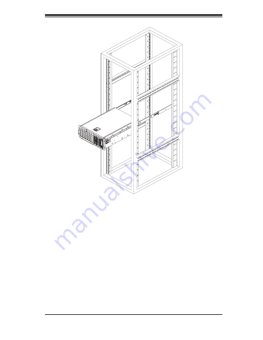
Figure 6-5.  Installing the Rack Rails

To install the chassis into a rack

1. Confi rm that chassis includes the inner rails and the outer rails.  

2. Line chassis rails with the front of the rack rails (C).

3. Slide the chassis rails into the rack rails, keeping the pressure even on both 

sides (you may have to depress the locking tabs when inserting).  When the 

server has been pushed completely into the rack, you should hear the locking 

tabs "click".

Summary of Contents for SC745S2-800VB

Page 1: ...SC745TQ R800 B SC745S2 R800 B SC745TQ 800 B SC745S2 800V B USER S MANUAL 1 0 SUPER SC745 CHASSIS Series ...

Page 2: ... TO USE THIS PRODUCT OR DOCUMENTATION EVEN IF ADVISED OF THE POSSIBILITY OF SUCH DAMAGES IN PARTICULAR THE VENDOR SHALL NOT HAVE LIABILITY FOR ANY HARDWARE SOFTWARE OR DATA STORED OR USED WITH THE PRODUCT INCLUDING THE COSTS OF REPAIRING REPLACING INTEGRATING INSTALLING OR RECOVERING SUCH HARDWARE SOFTWARE OR DATA Any disputes arising between manufacturer and customer shall be governed by the laws...

Page 3: ...4U chassis features a unique and highly optimized design for dual core Xeon platforms The chassis is equipped with a 800W high efficiency power supply for superb power savings High performance fans provide ample optimized cooling for FB DIMM memory modules and 4 hot swap drive bays offers maximum storage capacity in a 4U form factor This document lists compatible parts available when this document ...

Page 4: ...SC745 Chassis Manual iv Notes ...

Page 5: ...this chassis model including the fans bays airflow shields and other components Chapter 4 System Interface Refer to this chapter for details on the system interface which includes the functions and information provided by the control panel on the chassis as well as other LEDs located throughout the system Chapter 5 Chassis Setup and Installation Refer to this chapter for detailed information on thi...

Page 6: ...ply specifications and compatible backplanes Not all compatible backplanes are listed Refer to our Web site for the latest compatible backplane information Appendix A Chassis Cables Appendix B Power Supply Specifications Appendix C SAS 743TQ Backplane Manual Appendix D SCA 743S Backplane Manual ...

Page 7: ...rives 1 2 Other Features 1 2 1 4 Contacting SuperMicro 1 3 Chapter 2 System Safety 2 1 Overview 1 2 2 Warnings and Precautions 1 2 3 Preparing for Setup 1 2 4 Electrical Safety Precautions 2 2 5 General Safety Precautions 3 2 6 System Safety 3 Chapter 3 Chassis Components 3 1 Overview 3 1 3 2 Components 3 1 Chassis 3 1 Backplane 3 1 Fans 3 1 Mounting Rails optional 3 1 Power Supply 3 2 Air Shroud ...

Page 8: ...nfiguration 5 4 To rotate the storage module for rack mounting 5 5 Adding Drives to the Storage Module 5 6 To add up to three hard drives to the drive trays 5 7 To add up to three peripheral drives DVD ROM CD ROM floppy drive etc to the drive trays 5 9 To add five hard drives using a SuperMicro mobile rack 5 11 5 4 Installation Step 2 Install Hard Drives 5 13 To install hard drives to the chassis 5 1...

Page 9: ...ions 6 2 General Server Precautions 6 2 Rack Mounting Considerations 6 2 Ambient Operating Temperature 6 2 Reduced Airflow 6 3 Mechanical Loading 6 3 Circuit Overloading 6 3 Reliable Ground 6 3 6 5 Rack Mounting Instructions 6 6 Removing the Chassis Cover and Feet 6 6 To remove the chassis top cover 6 7 To remove the chassis feet 6 7 Identifying the Sections of the Rack Rails 6 8 To install the cha...

Page 10: ... A 1 A 3 Cables Included with SC745S Chassis SCSI A 1 A 4 Compatible Cables A 2 Alternate SAS SATA Cables A 2 Extending Power Cables A 3 Front Panel to the Motherboard A 3 Appendix B SC745 Power Supply Specifications Appendix C SCA 743S2 Backplane Manual Appendix D SAS 743TQ Backplane Manual Appendix E CSE M35S CSE M35T1 Mobile Rack ...

Page 11: ...Shipping List Part Numbers Please visit the following link for the latest shipping lists and part numbers for your particular chassis model http www supermicro com products chassis 4U chs 745 Chapter 1 Introduction 1 1 SC745 Chassis Model CPU HDD I O Slots Power Supply SC745TQ R800 B DP Dual core Xeon 8x SAS SATA 7x FF 800W Redundant SC745S2 R800 B DP Dual core Xeon 8x U320 SCSI 2 Channel 7x FF 80...

Page 12: ...are hot swappable Once setup correctly these drives can be removed without powering down the server In addition these drives support SAF TE SCSI and SES2 SAS SATA I O Expansion slots Each version of the SC745 Chassis includes seven full I O expansion slots Peripheral Drives Each SC745 Chassis provides three 5 25 Peripheral Drive Bays for Floppy Drive DVD ROM CD ROM Drive or additional hard drives ...

Page 13: ...ss SuperMicro Computer B V Het Sterrenbeeld 28 5215 ML s Hertogenbosch The Netherlands Tel 31 0 73 6400390 Fax 31 0 73 6416525 Email sales supermicro nl General Information support supermicro nl Technical Support rma supermicro nl Customer Support Asia Pacific Address SuperMicro Taiwan 4F No 232 1 Liancheng Rd Chung Ho 235 Taipei County Taiwan R O C Tel 886 2 8226 3990 Fax 886 2 8226 3991 Web Site ...

Page 14: ...SC745 Chassis Manual 1 4 Notes ...

Page 15: ...aim with carrier who delivered your system Decide on a suitable location for the rack unit that will hold that chassis It should be situated in a clean dust free area that is well ventilated Avoid areas where heat electrical noise and electromagnetic fields are generated You will also need it placed near at least one grounded power outlet When con figured the SC745 chassis includes one power supply ...

Page 16: ...em When working around exposed electrical circuits another person who is fa miliar with the power off controls should be nearby to switch off the power if necessary Use only one hand when working with powered on electrical equipment This is to avoid making a complete circuit which will cause electrical shock Use extreme caution when using metal tools which can easily damage any electrical componen...

Page 17: ...you if they come into contact with printed circuit boards or areas where power is present After accessing the inside of the system close the system back up and secure it to the rack unit with the retention screws after ensuring that all connections have been made 2 6 System Safety Electrostatic discharge ESD is generated by two objects with different electrical charges coming into contact with eac...

Page 18: ...a wrist strap Handle a board by its edges only do not touch its components peripheral chips memory modules or contacts When handling chips or modules avoid touching their pins Put the serverboard and peripherals back into their antistatic bags when not in use For grounding purposes make sure your computer chassis provides excel lent conductivity between the power supply the case the mounting faste...

Page 19: ...ling fans and one sometimes two power supplies SC745 models come in beige and black Backplane Each SC745 chassis comes with a 4U backplane Depending on your order your backplane will accept SAS SATA or SCSI For more information regarding compat ible backplanes view the appendices found at the end of this manual In addition visit our Web site for the latest information http www supermicro com Fans ...

Page 20: ... needed Always use the air shroud included with your chassis 3 3 Where to get Replacement Components Though not frequently you may need replacement parts for your system To en sure the highest level of professional service and technical support we strongly recommend purchasing exclusively from our Supermicro Authorized Distributors System Integrators Resellers A list of Supermicro Authorized Distr...

Page 21: ... to keep you constantly informed of the overall status of the system as well as the activity and health of specific components Most SC745 models are two buttons on the chassis a control panel a reset button and an on off switch This chapter explains the meanings of all LED indicators and the appropriate response you may need to take Figure 4 1 Front LEDs ...

Page 22: ...s has five LEDs These LEDs provide you with critical information related to different parts of the system This section explains what each LED indicates when illuminated and any corrective action you may need to take Overheat Fan Fail When this LED flashes it indicates a fan failure When continuously on not flashing it indicates an overheat condition which may be caused by cables obstructing the airflo...

Page 23: ...flashing Power Indicates power is being supplied to the system s power supply units This LED should normally be illuminated when the system is operating 4 4 Drive Carrier LEDs Your chassis uses SAS SATA or SCSI drives but not both SAS SATA Drives Each SAS SATA drive carrier has two LEDs Green Each Serial ATA drive carrier has a green LED When illuminated this green LED on the front of the SATA driv...

Page 24: ...anagement software SCSI Drives Each SCSI drive carrier has two LEDs Green When illuminated the green LED on the front of the SCSI drive car rier indicates drive activity A connection to the SCSI SCA backplane enables this LED to blink on and off when that particular drive is being accessed Red The SAF TE compliant backplane activates the red LED to indicate a drive failure If one of the SCSI drive...

Page 25: ...eral Maintenance Power Supply 5 2 Installation Steps Step 1 Remove Chassis Cover and Front Cover Step 2 Configure the Storage Module Step 3 Install Hard Drives Step 4 Install Motherboard Step 4 Install Air Shroud and Check Airflow Review the warnings and precautions listed in the manual be fore setting up or servicing this chassis These include infor mation in Chapter 2 System Safety and the warning...

Page 26: ...e cover latch button to release the latch handle 2 Pull the cover off the chassis using the latch handle Figure 5 1 Removing the Chassis Cover Front Cover To replace the chassis cover 1 With the latch handle open 2 Pull the cover off the chassis using the latch handle Cover Latch Handle Cover Latch Button ...

Page 27: ...drives The cover can be locked to prevent unauthorized access The key to this lock is shipped with the system To remove the front cover 1 Unlock the front cover using the key shipped with the system 2 Pull the cover open using the handle near the lock Front Cover Front Cover Lock Figure 5 2 Opening the Front Cover ...

Page 28: ...ation The SC745 chassis is shipped in tower mode and can be immediately used as desktop server If the chassis is to be used in a rack you must turn the storage module 90 degrees This can be done before during or after setup Figure 5 4 Chassis in Rack Mount Mode Figure 5 3 Chassis in Tower Mode Storage Module ...

Page 29: ...e to any component in the chassis 3 Push the storage module release lever This lever unlocks the storage mod ule 4 Grasp the external edges of the storage module and pull the unit from the chas sis 5 Turn the Storage Module 90 degrees as illustrated 6 Reinsert the module into the chassis and reconnect the cords Storage Module Release Lever Storage Module Figure 5 5 Remove the Storage Module ...

Page 30: ...e of three ways A Add up to three extra hard drives to the drive trays B Add up to three peripheral drives CD ROM DVD ROM etc drive trays C Add five hot swappable hard drives to the storage module This configuration requires a mobile rack More information on mobile rack installation can be found in the appendices at the end of this manual Figure 5 6 Chassis Storage Module ...

Page 31: ...elease Tabs To add up to three hard drives to the drive trays 1 Open the chassis cover 2 Locate the drive tray release tab for the slot you want to place the peripheral drive 3 Push the drive tray toward the front of the chassis Figure 5 7 Remove Drive Tray ...

Page 32: ...your motherboard The hard drive may not completely fill the tray 5 Secure the hard drive to the tray with four screws from the bottom 6 Slide the hard drive into the chassis until the tray clicks into place 7 Repeat these steps for each hard drive tray Hard Drive Hard Drive Tray Figure 5 8 Add a Hard Drive to the Drive Tray ...

Page 33: ... up to three peripheral drives DVD ROM CD ROM floppy drive etc to the drive trays 1 Open the chassis cover 2 Locate the drive tray release tab for the slot you want to place the peripheral drive 3 Push the drive tray toward the front of the chassis Figure 5 9 Remove Drive Tray ...

Page 34: ...ide 5 Attach the rails to a DVD ROM CD ROM floppy drive or other peripheral The rails should fit any standard sized peripherals 6 Slide the peripheral into the chassis until the tray clicks into place 7 Repeat these steps for each hard drive tray Hard Drive Rails Hard Drive Tray Figure 5 10 Add Hard Drive Rails to the DVD ROM Drive ...

Page 35: ...hot swappable hard drives The mobile rack goes into the storage module which goes into the chassis For more information on mobile rack installation and use refer to the appendix located at the end of this manual 1 Open the chassis cover 2 Locate the drive release tabs 3 Pull the first drive release tab and push the drive tray toward the front of the chassis Repeat this for all three tabs Figure 5 1...

Page 36: ...OM floppy drive or other peripheral The rails should fit any standard sized peripherals Hard Drive Rails Hard Drive Tray Figure 5 12 Remove the Hard Drive Rails Figure 5 13 Add Hard Drive Rails to Storage Rack 6 Install all six hard drive rails to the mobile rack Each individual rail requires two screws Also make sure the arrow on the rail points toward the front of the chassis 7 Slide the mobile ra...

Page 37: ...hese carriers also help promote proper airflow for the drive bays 1 Unlock and open the chassis cover 2 Press the release button to extend the drive tray handle 3 Using the handle pull the drive tray out by the handle The drive is hot swappable there are no cables to disconnect Drive Tray Handle Release Button Figure 5 14 Install Hard Drives 5 5 Installation Step 3 Install Hard Drives ...

Page 38: ...s To do this 7a Press the hard drive release button to extend the drive tray handle 7b Insert the hard drive into the chassis and close the handle to lock the hard drive into place Figure 5 16 Install Hard Drive Drive Tray 4 Remove the screws holding the drive tray to the dummy drive 5 Place a hard drive in the drive tray SAS SATA or SCSI Hard Drive ...

Page 39: ...C745 Chassis I O Shield To install the I O shield 1 Review the documentation that came with your motherboard Become familiar with component placement requirements and precautions 2 Open the chassis cover 3 Choose the proper I O shield for the motherboard you are installing 4 With the illustrations facing the outside of the chassis place the shield into the space provided Once installed the motherb...

Page 40: ...ircuits by securing space between the motherboard and the chassis surface The SC745 chassis packaging includes optional standoffs hexagon shaped posts These standoffs accept the rounded Phillips head screws included in the SC745 accessories packaging Figure 5 18 Chassis Standoffs ...

Page 41: ...s required by your motherboard install standoffs in any areas that do not have a permanent standoff To do this A Place a hexagonal standoff screw through the bottom the chassis B Secure the screw with the hexagon nut rounded side up 5 Lay the motherboard on the chassis aligning the permanent and optional standoffs 6 Secure the motherboard to the chassis using the rounded Phillips head screws 7 Sec...

Page 42: ...cable 2 backplane Each cable has 3 connectors two Hard Drive HDD and one Floppy Drive FDD Attach the HDD connectors to the backplane If you are using a SuperMicro backplane the FDD con nector does not need to be attached 8 pin mother board cable 1 mother board Provides power to the motherboard CPU This cable has 2 black and 2 yellow wires 4 pin mother board cable 1 mother board Provides power to P...

Page 43: ... chassis such as PCI cards To install add on and expansion cards 1 Locate the release tab on the top of the PCI bracket 2 Gently apply pressure in the middle of the release tab to unlock the PCI Slot bracket 3 Pull the release tab upward Press the Middle of the Release Tab Lift the Release Tab Figure 5 19 Add on Card Expansion Card Port ...

Page 44: ...erboard To do this slide the PCI card with L bracket into the PCI slot and secure the card to the motherboard 6 Push the PCI bracket release tab down until it locks into place with an audible click 7 Secure the PCI card with the screw previously removed from the chassis 8 Repeat this process with each PCI card you want to install into the chassis Figure 5 20 Remove PCI card slot guard ...

Page 45: ...s to set up NOTE The air shroud includes tabs that can be removed if motherboard compo nents prevent the air shroud from fitting securely Remove tabs only if necessary To install the air shroud 1 Remove the chassis cover 2 Place air shroud in your chassis with the fan side touching the edge of the two fans closest to the power supply The other side should cover both the rear fans 3 Replace the chas...

Page 46: ... Make sure no wires or foreign objects obstruct air flow through the chassis Pull all excess cabling out of the airflow path or use shorter cables The control panel LEDs inform you of system status See Chapter 3 System Interface for details on the LEDs and the control panel buttons Installation Complete In most cases the chassis power supply and fans are pre installed If you need to install fans con...

Page 47: ...ce a system fan 1 Open the chassis cover and determine which fan has failed Because the fans are hot swappable the chassis does not have to be powered down 2 Press the fan release tab and lift the failed fan from the chassis Front fans must be pulled straight up Rear fans must be tilted forward and then pulled out of the housing 3 Place the new fan into the vacant space in the housing while making...

Page 48: ...re 5 24 Rear Chassis Fans To replace a rear chassis fan 1 Press the rear fan release tab 2 Pull the fan from the chassis top first 3 Place the new fan in the chassis bottom first 4 Push the fan fully into the housing until the fan clicks into place ...

Page 49: ...e second power supply when the first fails If your system has only one power supply the system shuts down in the unlikely event of a power failure 5 9 Power Supply To replace the power supply 1 Power down the server and unplug the power cord If your chassis includes a redundant power supply at least two power modules you can leave the server running and remove only one power supply 2 Push the relea...

Page 50: ...Chassis Manual 5 26 Notes ...

Page 51: ...al noise and electromagnetic fields are generated You will also need it placed near a grounded power outlet Be sure to read the Rack and Server Precautions in the next section 6 3 Preparing for Setup The box your chassis was shipped in should include two sets of rail assemblies two rail mounting brackets and the mounting screws you will need to install the system into the rack Please read this sect...

Page 52: ...efore you install the rails Install the heaviest server components on the bottom of the rack first and then work up Use a regulating uninterruptible power supply UPS to protect the server from power surges voltage spikes and to keep your system operating in case of a power failure Allow the hot plug hard drives and power supply modules to cool before touch ing them Always keep the rack s front door...

Page 53: ...o the connection of the equipment to the power supply circuitry and the effect that any possible overloading of circuits might have on overcurrent protection and power supply wiring Appropriate consideration of equipment nameplate ratings should be used when addressing this concern Reliable Ground A reliable ground must be maintained at all times To ensure this the rack itself should be grounded P...

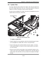
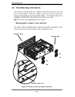
Page 54: ... will differ slightly You should also refer to the installation instructions that came with the rack unit you are using NOTE The outer rail is adjustable from 26 to 38 25 Removing the Chassis Cover and Feet The SC745 chassis is shipped with the chassis cover and feet pre installed Both the feet and cover must be removed for before installing the rails Chassis Cover Chassis Feet Figure 6 1 Remove F...

Page 55: ... top cover off the chassis To remove the chassis feet 1 Place the chassis on its side with the chassis side cover facing upward 2 Remove the screw holding the chassis foot in place 3 The foot lock is a tab located in the center of the foot that prevents the foot from sliding Using a flat head screwdriver gently lift the foot lock upward and slide the foot toward the rear of the chassis 4 Repeat ste...

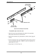
Page 56: ...rew Chassis Rail Screw Identifying the Sections of the Rack Rails The chassis package includes two rack rail assemblies in the rack mounting kit Each assembly consists of two sections an inner fixed chassis rail that secures directly to the server chassis and an outer fixed rack rail that secures directly to the rack itself ...

Page 57: ...le with the front of the chassis and secure with the three chassis handle screws 3 Repeats steps 1 and 2 with the other handle 4 Locate the inner rails 2 and screws 12 in the shipping package 5 Align the inner rails against the chassis as shown Confirm that the rails are flushed against the edge of the chassis 6 Tighten the screws Do not over tighten 7 Repeat steps 5 and 6 with the other inner rail ...

Page 58: ... the proper distance so that the rail fits snugly into the rack 3 Secure the front side of the outer rail with two M5 screws and the rear side of the outer rail with three M5 screws NOTE The outer rail is adjustable from approximately 26 to 38 25 4 Repeat steps 1 3 for the left outer rail Secure to the Front of the Rack Secure to the Rear of the Rack Figure 6 4 Assembling the Outer Rails Attach to ...

Page 59: ...des the inner rails and the outer rails 2 Line chassis rails with the front of the rack rails C 3 Slide the chassis rails into the rack rails keeping the pressure even on both sides you may have to depress the locking tabs when inserting When the server has been pushed completely into the rack you should hear the locking tabs click ...

Page 60: ...need to return the chassis to tower mounting To install the chassis cover 1 Remove the rack mount ears 2 Align the cover post with the corresponding holes on the top of the chassis and place the cover on top of the chassis The cover should overhang approxi mately one half inch over the front of the chassis 3 Slide the chassis cover toward the rear of the chassis to lock the cover into place Chassi...

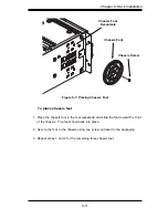
Page 61: ...e and slide the foot toward the front of the chassis The foot should lock into place 2 Secure the foot to the chassis using one screw enclosed in the packaging 3 Repeat steps 1 and 2 for the remaining three chassis feet Chassis Foot Receptacle Chassis Foot Figure 6 7 Placing Chassis Feet Chassis Screw ...

Page 62: ...Chassis Manual 6 12 Notes ...

Page 63: ...dicies Appendicies Appendix A Compatible Cables Appendix B SC745 Power Supply Specifications Appendix C SCA 743S2 Backplane Manual Appendix D SAS 743TQ Backplane Manual Appendix E CSE M35S CSE M35T1 Mobile Rack ...

Page 64: ...Appendicies 2 Notes ...

Page 65: ... 16 pin to 16 pin ribbon cable for control panel CBL 0139L Wire 50 cm IDE 80 Wire cable for DVD ROM CBL 0044L Cable 24 Serial ATA Lead free CBL 0209L Cable 210mm 4 to 3 pin fan power cable 3 CBL 0180L SATA various Set for 4 SATA Cables Length var ied to minimize airflow interference Cable 6 Regional power cord X2 for redun dant power supply models A 3 Cables Included with SC745S Chassis SCSI SC745S...

Page 66: ...75L Alt Name Big Four Alternate SAS SATA Cables Some compatible motherboards have different connectors If your motherboard has only one SAS connector that the SAS SATA cables must share use one of the following cables These cables must be purchased separately Description This cable has one ipass SFF 8087 mini sas connector 36 pins at one end and 4 SAS connectors on one end This cable connects from...

Page 67: ...20 pin CBL 0059 7 9 20 CM 8 pin CBL 0062 7 9 20 CM 4 pin CBL 0060 7 9 20 CM Front Panel to the Motherboard The SC745 chassis includes a cable to connect the chassis front panel to the motherboard If your motherboard uses a different connector use the following list to find a compatible cable Front Panel to Motherboard Cable Ribbon Cable Number of Pins Front Panel Number of Pins Motherboard Cable Pa...

Page 68: ...Chassis Manual A 4 Notes ...

Page 69: ...ifications Appendix B SC745 Power Supply Specifications This appendix lists power supply specifications for your chassis system 800W Redundant X2 MFR Part PWS 801 1R Rated AC Voltage 100 240V 50 60Hz 10 4 Amp 5V standby 4 Amp 12V 66 Amp ...

Page 70: ...Chassis Manual B 2 Notes ...

Page 71: ...Rev 1 0 SCA 743S2 Backplane USER S GUIDE JP13 JP10 ...

Page 72: ... PRODUCT OR DOCUMENTATION EVEN IF ADVISED OF THE POSSIBILITY OF SUCH DAMAGES IN PARTICULAR THE VENDOR SHALL NOT HAVE LIABILITY FOR ANY HARDWARE SOFTWARE OR DATA STORED OR USED WITH THE PRODUCT INCLUDING THE COSTS OF REPAIRING REPLACING INTEGRATING INSTALLING OR RECOVERING SUCH HARDWARE SOFTWARE OR DATA Any disputes arising between manufacturer and customer shall be governed by the laws of Santa Cl...

Page 73: ...l Safety Guidelines 1 1 1 3 An Important Note to Users 1 1 Chapter 2 Jumper Settings and Pin Definitions 2 1 Front Connectors and Jumpers 2 1 2 2 Front Connector and Pin Definitions 2 2 2 3 Front Jumper Locations and Pin Definitions 2 4 2 4 Rear Connectors and LED Indicators 2 5 2 5 SCSI Super Gem Installation Instrutions for Windows OS 2 6 ...

Page 74: ...iv SCA 743S Backplane User s Guide Notes ...

Page 75: ...ts edges only do not touch its components peripheral chips memory modules or gold contacts When handling chips or modules avoid touching their pins Put the card and peripherals back into their antistatic bags when not in use 1 2 General Safety Guidelines Always disconnect power cables before installing or removing any components from the computer including backplane Disconnect the power cable befo...

Page 76: ...1 2 SCA 743S Backplane User s Guide Notes ...

Page 77: ... Specifications JP13 JP10 Front Connectors Chapter 2 Jumper Settings and Pin Definitions 2 1 Front Connectors and Jumpers 1 GEM 318 Chips 2 Backplane Main 4 Pin PWR JP10 and JP15 3 SCSI Channel A LVD1 4 SCSI Channel B LVD2 3 1 2 4 Buzzer 1 ...

Page 78: ...mation to the user through the LED indicators and buzzers This function is only available when a RAID controller with a Raid set is present and enabled SAF TE LED Indicators LED Location Description D4 Front Overheat or Drive Failure red light flashing buzzer on D5 Rear A ID 0 Fail LED red light flashing buzzer on D6 Rear A ID 1 Fail LED red light flashing buzzer on D16 Rear A ID 2 Fail LED red light...

Page 79: ... 6 46 DB 6 13 DB 7 47 DB 7 14 DB P 48 DB P 15 Ground 49 Ground 16 DIFFSENS 50 Ground 17 TERMPWR 51 TERMPWR 18 TERMPWR 52 TERMPWR 19 Reserved 53 Reserved 20 Ground 54 Ground 21 ATN 55 ATN 22 Ground 56 Ground 23 BSY 57 BSY 24 ACK 58 ACK 25 RST 59 RST 26 MSG 60 MSG 27 SEL 61 SEL 28 C D 62 C D 29 REQ 63 REQ 30 I O 64 I O 31 DB 8 65 DB 8 32 DB 9 66 DB 9 33 DB 10 67 DB 10 34 DB 11 68 DB 11 3 and 4 Ultra...

Page 80: ...pad on the printed circuit board Note On two pin jumpers Closed means the jumper is on and Open means the jumper is off the pins Connector Pins Jumper Setting 3 2 1 3 2 1 Jumper Settings Jumper Jumper Settings Note JP14 Closed Enabled Open Disabled A Delay Start Enable JP18 Closed Enabled Open Disabled Buzzer Enable JP20 Closed Enabled Open Disabled B Delay Start Enable JP22 Closed Enabled Open Di...

Page 81: ...2 5 Safety Information and Technical Specifications Backplane LED LED STATE SPECIFICATION D4 ON Overheat Drive Failure LED Indicator Red light flashing Buzzer On FRONT LED INDICATORS ...

Page 82: ...SCA HDD 6 SCA7 B ID 3 SCA HDD 7 D25 D24 D23 D21 D22 D20 D17 D15 D27 D26 D16 D14 D6 D13 D5 D12 SCA1 SCA8 SCA2 SCA3 SCA4 SCA5 SCA6 SCA7 Rear LED Indicators Rear LED Connector Number Hard Drive Activity Failure LED SCA1 A ID 0 D12 A ACT1 D5 A FAIL1 SCA8 A ID 1 D13 A ACT2 D6 A FAIL2 SCA2 A ID 2 D14 A ACT3 D16 A FAIL3 SCA3 A ID 3 D26 A ACT4 D27 A FAIL4 SCA4 B ID 0 D15 A ACT5 D17 A FAIL5 SCA5 B ID 1 D20...

Page 83: ...nd CD ROM drives 7 Select Specify a location and choose Next 8 Click on Browse and choose D drive or wherever Supermicro Setup CD is in 9 Choose Qlogic folder and click on Open 10 System will automatically detect the GEM318 chip and install the drive from this point on Windows Driver Installation Procedure B 1 Right click the My Computer icon on your desktop and choose Properties 2 Click on the Ha...

Page 84: ...2 8 SCA 743S Backplane User s Guide Notes ...

Page 85: ...lane USER S GUIDE 12V 12V GND GND GND GND 5V 5V 48 1 16 64 49 H12 H 7 M 6 8 M 7 0 M 7 1 M72 M73 M75 M76 M80 M81 M82 M83 M84 M85 M86 M87 H5 H6 H3 M88 M89 M90 M 9 1 M 9 2 M93 M94 M95 M96 M97 MM2 MM3 SAS743TQ REV 3 00 R SUPER pb ...

Page 86: ... Front Connectors 1 4 A 3 Front Connector Pin Definitions 1 5 A 4 Front Panel LED 1 5 A 5 Front Jumpers and Pin Definitions 1 6 A 6 Front Rear SAS Connectors and Locations 1 7 B Rear SAS Connectors and LED Indicators 1 8 B 1 Rear Connector LED Indicator Locations 1 8 B 2 Rear Connector LED Indicator Descriptions 1 9 B 3 The AMI MG9072 SES 2 Controller SCSI Enclosure Services 2 LED Indicators 1 10 Us...

Page 87: ...ly do not touch its components peripheral chips memory modules or gold contacts When handling chips or modules avoid touching their pins Put the card and peripherals back into their antistatic bags when not in use General Safety Guidelines Always disconnect power cables before installing or removing any components from the computer including the SAS 743TQ Backplane Disconnect the power cable befor...

Page 88: ... Pin PWR Connector 3 JP26 Activity In LED Header 4 JP45 I2 C Connector 2 5 JP44 I2 C Connector 1 6 JP52 SideBand 2 7 JP51 SideBand 1 8 MG9072 1 2 3 4 5 6 8 Front View 7 JP18 JP29 JP38 JP50 MG 9072 JP36 JP33 D3 JP40 JP41 JP34 JP37 JP42 JP43 SAS 0 SAS 1 SAS 2 SAS 3 SAS 4 SAS 5 SAS 6 SAS 7 A 2a Front SAS Connectors Locations J5 SAS 0 J6 SAS 1 J7 SAS 2 J8 SAS 3 J10 SAS 4 J12 SAS 5 J14 SAS 6 J16 SAS 7 ...

Page 89: ...ed at JP52 JP51 on the front panel For SAS II to work properly please connect an 8 pin Sideband cables to JP52 JP51 as shown on the right See the table for pin definitions 6 5 8 7 10 9 Controller ID Backplane ID GND SB1 No Connection 4 3 Reset 1 2 SB6 SB5 Backplane Addressing SB0 SB2 GND SB4 SDA SB3 SCL SB7 Sideband Pin Definitions JP51 No Connection 3 Activity LED Header JP26 Pin Definitions 8 AMI ...

Page 90: ...37 Note Backplane ID 2 1 2 ID 0 2 3 ID 1 2 3 Note 2 3 JP38 I2 C Reset 2 On I2 C Off SGPIO Off On JP40 I2 C Reset_SDOUT 1 On SGPIO Off I2 C On Off JP41 I2 C Reset_SDOUT 2 On SGPIO Off I2 C On Off JP42 I2 C Backplane ID_SDIN 1 1 2 SGPIO 2 3 I2 C 1 2 2 3 JP43 I2 C Backplane ID_ SDIN 2 1 2 SGPIO 2 3 I2 C 1 2 2 3 JP50 I2 C Reset 1 On I2 C Off SGPIO Off On Note For the SGPIO setting to work properly for...

Page 91: ... Rear SAS Connectors and Locations A C T 2 M9 MM3 Rear View SAS 0 SAS 1 SAS 2 SAS 3 SAS 4 SAS 5 SAS 6 SAS 7 Front Panel Location SAS Connector Back Panel Location J5 Front View SAS 0 J1 Rear View J6 Front View SAS 1 J2 Rear View J7 Front View SAS 2 J3 Rear View J8 Front View SAS 3 J4 Rear View J10 Front View SAS 4 J9 Rear View J12 Front View SAS 5 J11 Rear View J14 Front View SAS 6 J13 Rear View J...

Page 92: ...r s Guide A C T 2 M9 MM3 Rear View D26 B Rear Connectors and LED Indicators B 1 Rear SAS Connector LED Indicator Locations D8 D1 4 D7 D13 D6 D5 D12 D19 D18 D20 D2 1 D23 D2 2 D15 D25 SAS 0 SAS 1 SAS 2 SAS 3 SAS 4 SAS 5 SAS 6 SAS 7 ...

Page 93: ...S 4 HDD connected to HDD J11 SAS 5 HDD connected to HDD J13 SAS 6 HDD connected to HDD J15 SAS 7 HDD connected to HDD Rear LED Indicators Specification D12 SAS 0 Activity LED D13 SAS 1 Activity LED D14 SAS 2 Activity LED D15 SAS 3 Activity LED D18 SAS 4 Activity LED D21 SAS 5 Activity LED D22 SAS 6 Activity LED D25 SAS 7 Activity LED D5 SAS 0 Failure LED D6 SAS 1 Failure LED D7 SAS 2 Failure LED D...

Page 94: ...to the table below for the information on SES 2 LED Indicators Front LED State Specification D3 Front On Overheat or Drive Failure Rear LED Indicators Specification D5 SAS 0 Failure LED D6 SAS 1 Failure LED D7 SAS 2 Failure LED D8 SAS 3 Failure LED D19 SAS 4 Failure LED D20 SAS 5 Failure LED D23 SAS 6 Failure LED D26 SAS 7 Failure LED Failure LED Patterns with SMC s Onboard SAS I 2 C Controller St...

Page 95: ...1 0 SUPER USER S GUIDE Mobile Rack CSE M35S CSE M35T1 ...

Page 96: ...SUPER CSE M35S CSE M35T1 User s Guide 2 Table of Contents 1 Packaging List 3 2 Technical Specifications 4 3 Jumper Settings 5 4 Installation Procedures 7 ...

Page 97: ... provide configuration flexibility and maximum data integrity 1 Packing List Please check to see if you have received all the items listed below CSE M35S CSE M35T1 Mobile Rack 90mm Exhaust Fan Fan 0057 Screws Thirteen 13 counts of Flat Head Screws Twenty four 24 counts of Round Head Screws Seven 7 counts of Round Head Screws with Lock Washer Drive Carrier Five 5 CSE PT17 CSE PT17 B black For CSE M...

Page 98: ...ptacle Connectors SATA hot swap hard drives CSE M35T 1 only Cooling Subsystem One 1 90mm 9cm Exhaust Fan System Monitoring Fan Fail Detection LED and Alarm Overheat LED indication Drive Fail Alarm and Indication CSE M35S only Built in Termination CSE M35S only Dimension WxHxD 146mm x 129mm x 245mm 5 7 in x 5 0 in x 9 6 in Weight Net 5 9lb 2 9 kg Gross 7 5lb 3 7 kg Chassis supported SC762 SC830 SC9...

Page 99: ...fault JP21 SCSI Termination Closed Enable Default Open Disable JP24 SCSI ID Selection 1 2 SCSI Ids 0 1 2 3 4 Default 2 3 SCSI Ids 9 10 11 12 13 JP29 GEM 318 IDs 1 2 ID6 Default 2 3 ID8 JP30 Fan Sense Pins 1 2 Enable Default If a fan is not present the alarm will sound Pins 2 3 Disable Jumper Settings JP29 JP21 JP30 JP18 JP24 Pin 1 Pin 1 Pin 1 Pin 1 Pin 1 ...

Page 100: ...26 Activity LEDs Pin Definitions Act LED 1 Act LED 2 Act LED 3 Act LED 4 Act LED 5 Channel 1 Channel 2 Channel 3 Channel 4 Channel 5 Jumper Description Setting JP18 Buzzer Reset Closed Enable Open Disable Default JP25 Overheat Temperature Open 45O C 1 2 50O C Default 2 3 55O C SATA LED Cable JP28 Fan Sense 1 2 Enabled if a fan is not present the alarm will sound Default 2 3 Disabled JP26 Act 1 Act...

Page 101: ...s shown below 4 Installation Procedures Installation Procedures Note For the CSE M35S 1 SCSI IDs are assigned automatically by the backplane Do not set IDs manually on the drives See the previous section for SCSI ID jumper settings 2 SCSI termination is enabled by default on the SCSI backplane ...

Page 102: ...SUPER CSE M35S CSE M35T1 User s Guide 8 3 Mount a drive in a carrier as shown below 2 Swing the handle outward and pull out the unit as shown below ...

Page 103: ...e low 2 Pull out the fan as shown below Note For the SC 942 Chassis the CSE M35 Rear Exhaust Fan should not be used Instead the hot swappable 120mm Chassis Fans included with the SC 942 Chassis should be connected to the Backplane of the CSE M35S CSE M35T1 Mobile Rack Installation Procedures ...

Page 104: ... M35S CSE M35T1 User s Guide 10 C Accessing the Drive Backplane 1 Unscrew the screw located on the side of the unit as shown below 2 Pull out the Rear Bracket as shown below 3 Access the Backplane as shown below ...

Reviews: