A+ Server AS -2114GT-DNR User's Manual
42
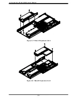
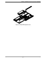
Installing Expansion Cards
The system has four low-profile (LP) PCIe Gen4 x16 slots for expansion add-on cards (AOCs,
such as RDMA, 200G IB, and 200G Ethernet) and one LP PCIe Gen4 x8 slot for an AOC up
to 100G or HBA/RAID. In addition, there is one mechanical LP slot for a RAID Battery Backup
Unit (BBU)/SuperCap/CacheVault. AOCs are recommended to be serviced by Supermicro
due to the optimized density of the 2U form factor.
Installing an Expansion Card
1. Power down the system, remove power cables and wait 30 seconds then remove cover.
Note:
Due to the weight of the system, this should not be attempted in the rack. The
system needs to be placed on a flat ESD-safe surface with ample support.
2. Begin by removing the riser assemblies from left to right (when viewed from the rear).
3. At the rear of the chassis, remove the PCI riser by unlatching the riser release (see
Figure 1-4 for locations). There are three at rear of the chassis and one for each riser
located at the metal chassis rear crossbar.
4. Slide the PCI riser out of expansion slot from the back of the chassis by lifting each riser
assembly vertically.
5. Once the riser releases are extended to the open position, lift each riser assembly
vertically. Be careful not to damage the power or data cables attached to the
assemblies. If more room is needed the cables can be detached, however, it is
important to note the cable numbers and their mated connectors.
6. Install and secure the expansion cards into the PCI riser.
7. Return and lock the PCI riser back into the back of the chassis and lock its release.
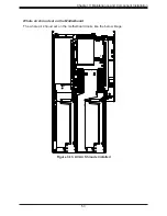
Figure 3-6. Installing Expansion Cards


