28 |
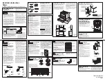
Anti-tip Device Installation
WARNING
TIPPING HAZARD:
To reduce the risk of property damage or personal injury; install anti-tipping device provided in accordance
with the installation instructions in this document.
Device must be engaged properly to prevent product from tipping over.
TIPPING
Kit enclosed with the range. Mark and drill
holes where the bracket will be located.
GROUND FIXING BRACKETS
Adjust the range height by regulating the feet , until you reach the desired cooktop height.
Fix the components B to the ground , according to width Y (see below chart).
24’’
30”
36”
48”
Y
22”
9/16
28”
35/64
34”
17/32
46”
17/32
Insert the component A in the hole in the back of the
cooker and measure the distance X (from the upper
edge of the hole to the ground).
Fix A to B with the screws , keeping the distance X.
Repeat the same sequence on the other side of the
product.
Slide the range towards the wall until the brackets A
are well into the holes in the back of the product.
Measure from floor to the anti-tip bar located
in a slit on the back of the range.
A
X
B
Y
=
=
X
Summary of Contents for R***241 Series
Page 1: ...Installation manual for all 24 30 36 and 48 ranges...
Page 33: ...33 Electric diagram 24 30 4 burners all gas ranges...
Page 34: ...34 Electric diagram 36 6 burners all gas ranges...
Page 35: ...35 Electric diagram 36 4 burners and griddle all gas ranges...
Page 36: ...36 Electric diagram 48 4 induction areas electric griddle and 2 gas burners...
Page 37: ...37 Electric diagram 48 6 gas burners and electric griddle all gas ranges...
Page 38: ...38 Electric diagram 30 4 burners dual fuel s c ranges Worktop Oven...
Page 39: ...39 Electric diagram 36 6 burners dual fuel s c ranges Worktop Oven...
Page 40: ...40 Electric diagram 48 6 burners and electric griddle dual fuel s c ranges Worktop Main Oven...
Page 42: ...42 Electric diagram 30 36 48 dual fuel s c ranges Oven...
Page 44: ...superiore us superiore ca 461308626 rev 002 10 2017...