


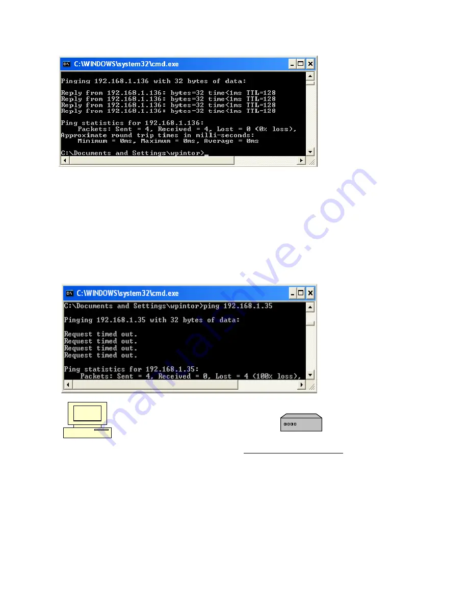
4. The Dos window will display “Reply from” the IP address 3 to 4 times. You will see “Packets sent = X, Received = X
and Lost = X. This will tell you that, you’ve successfully connected to your DVR and we can proceed. Like
FIG.2
below.
FIG.2
5. If you see “
Request timed out
” and “Packets: Sent X, Received = X, Lost = X” like
FIG.3
below, then you have not
established a LAN connection between the DVR and the computer. You will need to recheck all DVR network settings
above, check with IP provider or IT department, router settings. Make sure cables are good, and connected. This
could also be due to a bad cable between the DVR and router or bad DVR
Network Interface Controller (NIC).
Check
the Ethernet cable connection on the back of the DVR and check for green lights and that they blink when you “ping”
the DVR. If it is not blinking, this could indicate that the DVR’s network interface card is bad and call us for tech
support. If green light is blinking, as a fi nal check, connect the DVR
directly
to the computer using an Ethernet
“
crossover cable
”
(which is available at any electronics store such as Radio Shack, or Best Buy, Circuit City, etc…)
eliminating all other cables and equipment. Crossover cables are only used for testing purposes and repeat the
pinging process. If after connecting the crossover cable and you are successful in pinging your DVR, the problem is
with your router, cables or the IP address. Check with your IP provider, check your cables and make sure your router is
confi gured for port forwarding. If you’re not successful in pinging your DVR call Supercircuits for technical help.
FIG.3
---------------------------------------------------------------
PC
Ethernet Crossover Cable
DVR
6. If you’re looking at
FIG.2
then you have demonstrated that a Local Area Connection (LAN) has been made between
the DVR and the computer. Proceed to Software installation.
7. Install
the CD that came with your DVR into the PC and install
Video Web Server.
49
Summary of Contents for DMR 16 RT
Page 1: ...DVQ 2 DMR 4 8 16 RT USER MANUAL 1 ...
Page 13: ...13 2 2 DMR 4 8 16 RT Rear Panel ...
Page 17: ...DVR and Monitor Installation 3 2 DVQ 2 SYSTEM CONFIGURATION 17 ...
Page 18: ...3 2 DMR 4 8 16 RT SYSTEM CONFIGURATION 18 ...
Page 72: ...Appendix 4 DVQ 2 RECORDING TIME TABLE 72 ...
Page 74: ...Appendix 6 DMR 4 8 16 RT Compatible Hard Drives HDD 74 ...
Page 75: ...Appendix 7 DVQ 2 DMR 4 8 16 RT MENU TREE 75 ...
Page 76: ...Appendix 8 DMR 4 8 16 RT Specifications 76 ...


