Super Circuits DMR 16 RT User Manual Download Page 45

7.0  NETWORKING

          
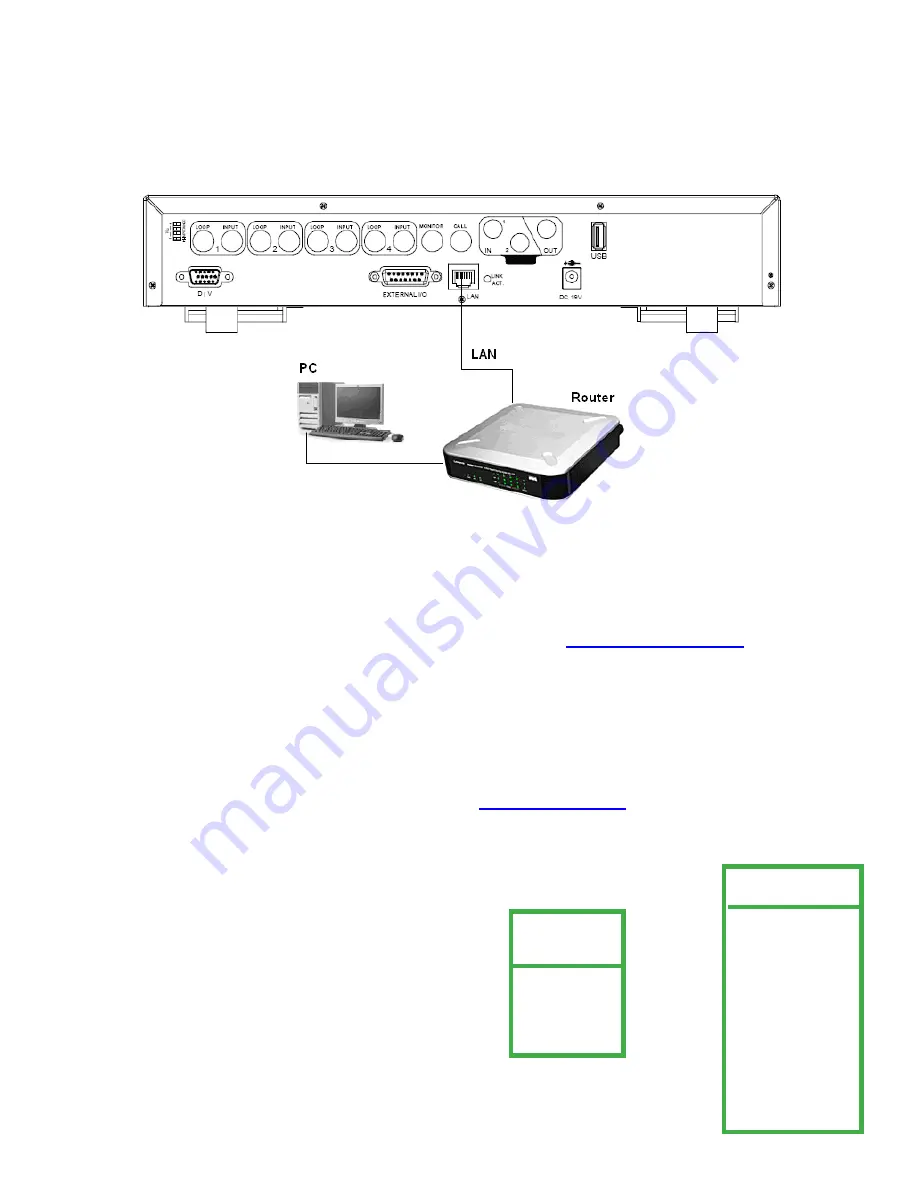
View video from your PC anywhere in the world by connecting your DVR LAN connection to your network system. 

7.1  Things to do before networking your DVR

1. Connect 

DVR LAN connection to your LAN router.  (Read Networking your DVR User Guide)

2. To connect to the world wide area network for remote viewing you 

must confi gure your router to allow port 

       forwarding.


Super Circuits does not provide technical support for router setup.  Contact your service provider/ router

       manufacturer for support on setting up port forwarding.  Use port number 

8000

.

3. Do 

you have a dynamic or static IP address?  Note: Static IP address is highly  recommended,  because of the video

       connection reliability.  Call your IP provider about setting up a static IP address for your DVR. 

4. Make 

sure you have DirectX version 9.0c on your computer.  If not go to  

www.microsoft.com/directx

5. Make 

sure that you have the following information from your IP provider or IT department:  

      
       A. IP address.
 

B. Subnet Mask. 


C. Default Gateway.  


D. If there is a DNS number. 


E. If DHCP settings are allowed set your DVR to “

Manual

” not “

Automatic

”.

      G. Next verify your IP address 

(for your domain) 

by going to 

www.whatismyip.com.

  This is the IP address you will use 

           to log in remotely.


  MENU

    RECORD
    TIMER
    DATE


 ADVANCE


 ADVANCE


CAMERA


DETECTION

   DISPLAY
   ALERT
   REMOTE
   SYSTEM
 

  NETWORK

   BACKUP
   HDD INFO
   EVENT LOG


1. Access 

your DVR network settings by going to 

MENU / ADVANCE/ NETWORK.

  Set 

IP, 

      ADDRESS, GATEWAY, NETMASK 

and

 WEB PORT.  

45

Summary of Contents for DMR 16 RT

Page 1: ...DVQ 2 DMR 4 8 16 RT USER MANUAL 1 ...

Page 2: ...SUPER CIRCUITS 11000 NORTH MOPAC EXPRESSWAY SUITE 300 Austin TX 78759 Phone 800 335 9777 Fax 866 2567 9777 2 ...

Page 3: ...th the radio interference requirements Disclaimer We reserve the right to revise or remove any content in this manual at any time We do not warrant or as sume any legal liability or responsibility for the accuracy completeness The content of this manual is subject to change without notice THIS PRODUCT IS LICENSED UNDER THE MPEG 4 VISUAL PATENT PORTFOLIO LICENSE FOR THE PERSONAL AND NON COMMERCIAL ...

Page 4: ...ve 22 4 5 Date Time 23 4 6 Overwrite 23 4 7 Motion Detection 24 4 8 Record Quality and IPS Images Per Second 25 5 MENU CONFIGURATION 28 5 1 Menu Introduction 28 5 2 Record 29 5 3 Timer 30 5 4 Date 31 5 5 Advance 31 5 6 Camera 32 5 7 Motion Detection 32 5 7 2 Detection Timer 35 5 8 Display 35 5 9 Alert 36 5 10 Remote 37 5 11 System 38 5 12 Network 39 5 13 Backup 39 5 14 HDD info 40 5 15 Event Log 4...

Page 5: ...earch List 59 7 14 Timer Record 60 7 15 Date 61 7 16 Record Setting 61 7 17 Alarm 62 7 18 General 62 7 19 Account 63 7 20 Online User Info 63 7 21 File Path 63 7 22 Operation via IE Browser 64 8 0 REMOTE PTZ Camera Control Panel 65 9 0 FAQ TROUBLESHOOTING 66 9 1 Default Value 67 APPENDIX 1 INSTALL HDD 67 APPENDIX 2 PIN CONFIGURATION 68 APPENDIX 3 RS 232 PROTOCOL 71 APPENDIX 4 RECORDING TIME TABLE ...

Page 6: ...ayback backup and network operations at the same time Free Upgrade to Advanced Functions Allow you to upgrade DVR functions without any charges Long Recording Hours 500GB can record more than 5 days 4CH Frame Best Quality 30IPS Backup Function Supports network remote recording backup Remote Surveillance Supports remote surveillance of up to 5 users simultaneously with licensed software AP and IE b...

Page 7: ...7 1 3 Package Contents DVQ unit 1 Power Supply 1 Power Cable 1 Manual 1 Software CD R 1 OR Power cord Power supply Software Manual DVQ 2 DMR 4 8 16 RT ...

Page 8: ...2 FRONT AND REAR PANELS 2 1 Front Panels 8 Power Menu Left Right keys Search Up Down keys Enter key Plus Minus keys DVQ 2 DMR 4 8 16 RT ...

Page 9: ... Display Position Under the live mode you can switch the positions of two channels by Step1 Press Set to highlight one channel Step2 Press UP DOWN LEFT RIGHT button to change the channel position Step3 Press or to select the channel Step4 Press ENTER button to confirm the setting Under the playback mode you can select a channel to display in live video Step1 Press Set to highlight one channel Step...

Page 10: ...back mode Press or button to pause stop playback Press or button to fast rewind forward 14 Audio Press SLOW and ZOOM buttons at the same time to select live or playback sound for audio channels 15 PTZ Press minus and SEQ plus buttons at the same time to enter exit the PTZ control In the PTZ control mode Zoom in Press button Zoom out Press button Adjust PTZ angle Press direction buttons to turn up ...

Page 11: ... the video playback In the Pause mode Press Right button once to get one frame forward Press Left button once to get one frame rewind Stop Pressing the stop button will return to live mode Channel Display Mode Display mode Press button to display 4 channels Full screen view Press the number buttons 1 4 to display the selected channel Note Under the playback mode you can select a channel to display...

Page 12: ...ction with video channel 1 6 Audio OUT Connect to a monitor or speaker with 1 mono audio output 7 USB file backup Note For the list of compatible USB flash drives refer to APPENDIX 5 COMPATIBLE USB FLASH DRIVE Page 63 8 D V Port Digital Video Port NOT USED 9 IR Connect the IR receiver for remote control 10 EXTERNAL I O Use the 15PIN DSUB to connect external devices external alarm PTZ camera etc Fo...

Page 13: ...13 2 2 DMR 4 8 16 RT Rear Panel ...

Page 14: ...nnect to CALL monitor Show the channel switch display When the alarm is triggered the call monitor will show the image of the triggered channel for a period of time 10 POWER Connect to the provided adapter 11 FAN For ventilation 12 VIDEO INPUT CHANNEL 1 16 CHANNEL 1 8 CHANNEL 1 4 Connect to video sources such as cameras 13 LOOP CHANNEL 1 16 CHANNEL 1 8 CHANNEL 1 4 Video output 14 75Ω HI IMPEDANCE ...

Page 15: ... the box for testing your cameras and cables You can use a TV set with a video input if you don t have a monitor Plug your monitor into a 110 120 AC power source Do not mistake the antenna input on the TV for a VIDEO INPUT Monitors and TV s have video inputs clearly marked The TV RCA input will look some what like the image below labeled VIDEO INPUT This type of input connector is called an RCA fe...

Page 16: ... AC power source and will not work properly with a 12V DC power source Do not use AC power supplies with Supercircuits EXT series cables such as EXT25 EXT50 or EXT100 Use the CAB BNC 25 CAN BNC 50 or CAB BNC 100 with AC power supplies Grab another camera and replace it with a 2nd camera If you have a good picture with the 2nd camera the first camera is not working properly Call SuperCircuits techn...

Page 17: ...DVR and Monitor Installation 3 2 DVQ 2 SYSTEM CONFIGURATION 17 ...

Page 18: ...3 2 DMR 4 8 16 RT SYSTEM CONFIGURATION 18 ...

Page 19: ...TRODUCTION This digital video recorder is designed to function right out of the box We made setting up your DVR easier by adjusting the time date and record settings for you Your DVR is set to record for 14 days with the video quality and frame rate set to the highest settings IConnect the AC Power Cord with Power Adapter and plug into an electrical AC outlet Turn your DVR on by hitting the power ...

Page 20: ...Y DEFAULT 2 CLEAR HARD DRIVE 3 SYSTEM TIME 4 OVERWRITE 5 MOTION DETECTION 6 RECORD SETTINGS BASIC MENU SETUP 1 Press the MENU key on the front panel to login The Menu allows you to configure your digital video recorder DVR settings 2 Use CH SELECTORS 1 16 to key in the password Power Menu Left Right keys Search Up Down keys Enter key Plus Minus keys DMR 4 8 16 RT DVQ 2 20 ...

Page 21: ...INUS and PLUS buttons to change values Press the ENTER button once and the MENU screen will appear NOTE If you get an error message Password Error you have entered an incorrect password MAIN MENU There are 4 options available in the Main Menu RECORD Record Setup TIMER Scheduling Record DATE Date Setup ADVANCE System Configuration KEY UNLOCK PASSWORD 0000 MENU RECORD TIMER DATE ADVANCE 21 ...

Page 22: ... KEYLOCK NEVER LANGUAGE ENGLISH VERSION 1088 10 K2 04 AA 11 VIDEO FORMAT NTSC 5 Use LEFT key to select YES and press the ENTER button The DVR will display a REBOOT dialog box beep and take a minute or two to Initialize Let s CLEAR the HDD 4 4 CLEAR HDD Return to the SYSTEM MENU and select CLEAR HDD and push the ENTER button RESET DEFAULT RESET DEFAULT ARE YOU SURE YES NO SYSTEM SERIAL TYPE RS 485 ...

Page 23: ...0 FORMAT Y M D DAYLIGHT SAVING ON Set OVERWRITE 4 6 OVERWRITE 9 Select RECORD from the main MENU Select OVERWRITE and change OVERWRITE NO to YES and push the ENTER key Select YES to confirm MENU RECORD TIMER DATE ADVANCE RECORD MANUAL RECORD ENABLE NO EVENT RECORD ENABLE YES TIMER RECORD ENABLE NO OVERWRITE YES RECORD IMG SIZE FRAME RECORD QUALITY BASIC MANUAL RECORD IPS 030 EVENT RECORD IPS 030 T...

Page 24: ... DETECTION TITLE DET AREA LS SS TS RE ALARM 01 ON SETUP 07 03 02 10 LOW 02 ON SETUP 07 03 02 10 OFF 03 OFF SETUP 07 03 02 10 LOW 04 OFF SETUP 07 03 02 10 HIGH PREV NEXT NOTE If you don t want the ALARM BUZZER to sound every time you have motion set INT BUZZER to OFF Set RECORD QUALITY and IPS ADVANCE CAMERA DETECTION ALERT REMOTE SYSTEM NETWORK HDD INFO EVENT LOG ALERT EXT ALERT ON INT BUZZER OFF ...

Page 25: ...ORD MANUAL RECORD ENABLE NO EVENT RECORD ENABLE YES TIMER RECORD ENABLE NO OVERWRITE YES RECORD IMG SIZE FRAME RECORD QUALITY BASIC MANUAL RECORD IPS 030 EVENT RECORD IPS 030 TIMER RECORD IPS 030 TOTAL IPS SHARE FIX MENU RECORD TIMER DATE ADVANCE Use Table 1 to set your RECORD QUALITY and IPS for DVQ 2 DVQ 2 TABLE 1 25 ...

Page 26: ...PS for DMR 4 8 16 RT DMR 16RT Table 2 1 Recording time varies depending on Different camera quality Different picture composition object movement 2 For DMR 8RT Record day multiply Record day by 2 For DMR 4RT Record day multiply Record day by 4 26 ...

Page 27: ...will flow better Real time video flow is not necessary for most applications NOTE All data in table 1 is estimated and you must test your QUALITY and IPS settings for your application to see your results Enter your QUALITY and IPS values in the RECORD menu Exit all menus by pressing the MENU button THIS CONCLUDES OUR RE CONFIGURE YOUR DVR AND YOU SHOULD BE OPERATIONAL PLEASE CONTINUE READING THE U...

Page 28: ...ODUCTION 28 Power Menu Left Right keys Search Up Down keys Enter key Plus Minus keys Press the MENU button and enter your password NOTE If you get an error message Password Error you have entered an incorrect password DMR 4 8 16 RT DVQ 2 ...

Page 29: ...o setup the record quality type and configuration Press the MENU button on the front panel to enter the main menu list and select RECORD and press the Enter button Remember to press the MENU button to exit after making your selections MENU RECORD TIMER DATE ADVANCE RECORD MANUAL RECORD ENABLE NO EVENT RECORD ENABLE YES TIMER RECORD ENABLE NO OVERWRITE YES RECORD IMG SIZE FRAME RECORD QUALITY BASIC...

Page 30: ...e for EVENT RECORD Recording is triggered by an alarm or motion event 9 TIMER RECORD IPS Select the number images per second for TIMER RECORD Recording is activated by a time schedule NOTE IPS options U S International NTSC PAL FRAME 30 15 7 3 FRAME 25 12 6 3 CIF 120 60 30 15 CIF 100 50 25 12 10 TOTAL IPS SHARE NOT AVAILABLE FOR THIS UNIT Controls how IPS is shared IPS share setting is fixed and w...

Page 31: ...er the main menu Select DATE and press ENTER 1 DATE Set the current date and time The default order is YEAR MONTH DATE HOUR MIN SEC 2 FORMAT Select one date format from the following 3 options Y M D M D Y D M Y 3 DAYLIGHT SAVING Select daylight savings time ON OFF If ON press ENTER to go into submenu for settings Set the start time and end time and adjust the daylight savings time in ADJUST The be...

Page 32: ...When activated the symbol will display on the screen 5 7 MOTION DETECTION 1 DETECTION SETUP Motion setup Select ADVANCE DETECTION DETECTION SETUP and press ENTER 1 TITLE Displays camera title set in CAMERA TITLE setup 2 DET Activate the motion detection for selected channels ON OFF Use ON to activate ADVANCE CAMERA DETECTION DISPLAY ALERT REMOTE SYSTEM NETWORK BACKUP HDD INFO EVENT LOG CAMERA TITL...

Page 33: ...arm or set off external alarms and start recording Make sure you are In ADVANCE DETECTION DETECTION SETUP Setup motion detection AREA and push the ENTER key The start area is indicated by the four cursors move the start cursor using the LEFT RIGHT UP and DOWN keys Push the ENTER key to enable motion start area and push ENTER key again to disable motion area The pink shaded area is the motion disab...

Page 34: ... TS Time of Sensitivity TS sensitivity detects how long one object stays in the detection area and triggers the recording The smaller the value is the higher sensitivity for motion detection The highest sensitivity setting is 00 and the lowest sensitivity setting is 15 The default setting is 02 7 RE Reference RE is to set a reference for detection The default value is 10 which means the DVR will c...

Page 35: ...information ON OFF ADVANCE CAMERA DETECTION DISPLAY ALERT REMOTE SYSTEM NETWORK BACKUP HDD INFO EVENT LOG DISPLAY TITLE DISPLAY ON DATE DISPLAY ON HDD INFO ON LOSS SCREEN BLUE PLAYBACK INFO NORMAL DWELL DURATION SEC 2 DE INTERLACE ON MONITOR OUT MAIN OSD SETUP WATERMARK ON DETECTION DETECTION SETUP DETECTION TIMER DETECTION TIMER DATE START END OFF 00 00 00 00 DAILY 08 00 18 00 SUN 06 00 23 00 MON...

Page 36: ... active WATERMARK feature Anytime backup video is modified the video image will turn to light red and the playback will pause Note WATERMARK is always on and cannot be turned off 5 9 Alert Select ALERT and press ENTER Menu path MENU ADVANCE ALERT 1 EXT ALERT Enable or disable sound when external alarm is triggered ON OFF 2 INT BUZZER Enable or disable sound ON OFF for all internal buzzers KEY BUZZ...

Page 37: ...of data will record before an alarm motion is triggered when PRE ALARM and EVENT RECORDING are enabled 5 10 Remote Select REMOTE and press ENTER 1 TITLE Displays camera title for each channel 2 DEVICE Select camera type 3 ID Set PTZ camera address 0 255 PTZ address is displayed on the screen 4 PROTOCOL Select NORMAL our protocol or P D PELCO D protocol 5 RATE Set baud rate 2400 4800 9600 19200 576...

Page 38: ...is model 9 R E T R MIN Does not apply for this model R E T R Activation Press MENU buttons on the front panel to enable R E T R 3 5 10 minutes later A message R E T R ON will be displayed in white text and after the RETR is activated a red message R E T R will display on the screen R E T R Off Press any key except or POWER buttons and enter the password to turn off RETR 10 AUTO KEYLOCK Set the MEN...

Page 39: ...1 USB BACKUP USB backup is not available on this model Before making a USB backup please check if the a USB flash drive is supported If the USB flash is not supported you will get a error message USB ERROR For a list of the compatible USB flash drives please refer to APPENDIX 5 Compatible USB Flash Drives page 63 b Format USB flash drive using FAT 32 using your PC c Verify USB flash drive is clear...

Page 40: ...NISH will display on the screen after CD backup is complete press EJECT button to eject CD Place CD into the PC CD ROM drive Convert to AVI format by double clicking on the file Note Supports Windows 2000 and Windows XP ADVANCE CAMERA DETECTION DISPLAY ALERT REMOTE SYSTEM NETWORK BACKUP HDD INFO EVENT LOG HDD INFO HDD NUM HDD SIZE HDD NUM HDD SIZE MASTER 1 368 SLAVE 1 NO HDD MASTER 2 NO HDD SLAVE ...

Page 41: ... Press SEARCH button on the front panel 3 SYSTEM LOG Show system error codes Reference error code list below SEARCH HDD MASTER FULL LIST RECORD LIST SYSTEM LIST ALARM LIST MOTION LIST EVENT SEARCH TIME SEARCH 1 HDD MASTER 1 Press ENTER to select HDD if there are more than 1 2 FULL LIST Show all recorded type files R RECORD S SYSTEM A ALARM MS MOTION T TIMER 3 RECORD LIST List of manual recorded fi...

Page 42: ...tor displays video Switch to PAL System or POWER Not used in the U S Press POWER button on front panel to shutdown Then press and hold 7 first and press POWER to switch to PAL system Press the buttons until the monitor displays video Note The DVR will automatically detect PAL NTSC You can also manually switch between PAL and NTSC 42 6 2 Switch NTSC PAL System For DMR 4 8 16 RT only 1 Press POWER b...

Page 43: ... page 31 Use Remote Video Server software on your CD to upgrade firmware see Video Server login panel page 43 At login page enter the user name password IP address and port Then press button to upgrade firmware or OSD language files The provided firmware and OSD files should be saved to your PC 6 4 Audio Backup and Playback For audio use channel CH1 Audio hardware connections 1 Connect camera audi...

Page 44: ...section 6 4 2 Detection at page 18 or section 2 Detection at page 40 AP software system configuration 2 Activate the R E T R Press Menu and buttons on the front panel at the same time this will activate R E T R in 3 5 10 minutes later R E T R ON will display on the screen in white text and after the RETR is activated the message R E T R will display on the screen and turn to red From AP software a...

Page 45: ...hly recommended because of the video connection reliability Call your IP provider about setting up a static IP address for your DVR 4 Make sure you have DirectX version 9 0c on your computer If not go to www microsoft com directx 5 Make sure that you have the following information from your IP provider or IT department A IP address B Subnet Mask C Default Gateway D If there is a DNS number E If DH...

Page 46: ...168 95 1 1 PORT 0080 STATIC IP 160 121 346 236 GATEWAY 160 121 346 236 NETMASK 255 255 255 254 5 In NETWORK menu select DNS and enter IP address of the domain server obtained from your ISP Internet Service Provider NETWORK NETWORK TYPE STATIC DNS 168 95 1 1 PORT 0080 6 Select PORT and enter 8000 6 Exit all menus by pressing the MENU key and turn your DVR off by hitting the power key and holding fo...

Page 47: ...stname For example use http www dyndns com Sign up for an account Log in with your account information and click My Service Click Add Host Services Click Add Dynamic DNS Host Fill in and choose the desired host name The host name is created You will be connected to the corresponding IP addresses whenever you enter this hostname Dynamic IP PPPOE 1 Build a Local Area Network LAN between the DVR and ...

Page 48: ... TYPE Type the User Name and Password given to you from your ISP Press APPLY button to confirm the setting 3 Set the DVR DDNS settings in the SYSTEM CONFIG using Video Server DDNS Choose Enable User Name Type your DDNS account Password Type your DDNS password Domain Type the Host Name EX securityanytime dyndns org System Name Choose the DDNS server where you applied the domain name EX dyndns After...

Page 49: ... the DVR s network interface card is bad and call us for tech support If green light is blinking as a final check connect the DVR directly to the computer using an Ethernet crossover cable which is available at any electronics store such as Radio Shack or Best Buy Circuit City etc eliminating all other cables and equipment Crossover cables are only used for testing purposes and repeat the pinging ...

Page 50: ...e the included CD disk into the CD ROM drive and install the Video Server and JAVA programs on to your PC During the software installation you will step through the dialog sequence below In some installations JAVA might not install because the files are already updated 50 ...

Page 51: ... the desktop For the latest AP software updates please check with your distributor 3 Double click Video Server on your PC to enter the login page Key in IP address 192 168 1 10 username admin password admin and port 8000 in the login page NOTE Factory default user name is ADMIN Password is ADMIN 51 ...

Page 52: ...de Firmware Press Upgrade Firmware button to upgrade DVR firmware or OSD language files The provided firmware and OSD files should be saved on PC first Player Press Player button to access and play the latest recorded file on your PC 7 6 Control Panel a Data Transfer Rate b Image Transfer Rate Per Second c Connect Disconnect d Resolution NTSC 320 228 640 450 PAL 320 276 640 552 e Image Quality Hig...

Page 53: ...irm the setting s Sequence Activate call monitor function and press again to exit When motion is detected the monitor will display motion triggered channel t Enter Used to confirm settings or enter a selection u PTZ Control On Off Use to select the PTZ device press OK button to enter selected PTZ Press ESC to exit from PTZ control v Menu Up Down Left Right Used to enter the PTZ menu w Not used R E...

Page 54: ...eliability PPPoE and DHCP network connection types are required to apply for a DDNS service Web Port The DVR can be viewed over the network with the Video Web Server or the IE web browser TCP port used by HTTP is 80 In some cases it is better to change this port number for added flexibility or security The valid web port number ranges from 1 to 9999 Static IP Use the Network menu choose a Static I...

Page 55: ... server where you applied for the domain name EX dyndns f Auto If you select DHCP option in Network menu g You can check the AUTO option to automatically assign the IP address 2 Mail When alarm trigger is triggered an e mail notification will send an e mail notification to the specified recipients once Enable the e mail notification in the Alarm menu Note Users can assign up to 4 mail accounts for...

Page 56: ...rd settings DEVICE Remotely title or name your cameras Use ID protocol and rate for PTZ type cameras 7 9 DVR Camera channels can be adjusted independently Select the desired camera channel and press Edit to enter 7 10 Detection Select the channel and press Edit button to enter the motion detection sensitivity and area setting page 56 ...

Page 57: ...arm polarity e Press OK and then press APPLY button to confirm 7 11 Network Backup You can backup recorded data from the DVR directly to your PC and CD through the network The backup file can be played in the PC with the remote Video Server or other media players Ex Windows Media Player or RealPlayer after the file is converted to AVI format Enter the backup information If you want to make a backu...

Page 58: ...g DVR Network Backup window will display Writing cd message and status bar When CD is completed the CD will eject and a DVR Network Backup pop up window will display Download process is finished message Press PLAY button to play the file or Exit to quit 7 12 VIDEO BACKUP PLAYER a Time Bar b Playback Information c Functions 1 De interlace Reduce vibration when pausing picture 2 De blocking Reduce v...

Page 59: ...pen previous video Pause playback press button to go to the previous frame 8 Open the next backup video Pause playback press button to go to the next frame d Playback Control Buttons Play Stop Pause Fast Rewind Fast Forward e Snapshot Press Snapshot to take a snapshot of the current image and save in specified destination f Close the Player HDD Number Select the hard drive with the recorded data L...

Page 60: ...imer Record Timer Record you can schedule up to 7 time events DATE Select a day from DATE dropdown menu Options OFF SUN MON TUE WED THU FRI SAT MON FRI SAT SUN and DAILY START Enter the start time END Enter the end time Press APPLY to confirm the setup or EXIT to quit without saving 60 ...

Page 61: ... set IPS Enable Schedule recording time NOTE IPS Images Per Second OVERWRITE Enable OVERWRITE YES NO Set DVR to record over previous video recordings and record new video when hard drive is full In the NO option the hard drive will stop recording when full and you will have to restart the recording manually RECORD IMG SIZE Choose FRAME or CIF FRAME mode will give you 30 images per second CIF mode ...

Page 62: ...ation set in General File Path and Snapshot Path Post Numbers Set the number of pictures to send 1 10 Alarm Duration Set motion trigger recording duration time 5 SEC 10 SEC 20 SEC 40 SEC Auto switch to alarm video Will switch to the video channel that an alarm event is coming from Alarm Refresh Press to clear the alarm icon 7 18 General View and setup DVR information and settings Firmware Version ...

Page 63: ...ferent user access a b c d e f g SUPERVISOR all system access HIGH all system access except for System Config g NORMAL Partial system access except for Connecting Disconnecting SnapShot and Record a e and f GUEST This level only allows to watch the video 7 20 Online User Info View online user account information 7 21 File Path View and change the file path for saving snapshots and recorded data To...

Page 64: ...in your DVR IP address in the URL address box and press Enter 2 Enter your DVR Username and Password If you have not made any changes to the Admin Username or Password type Admin in for the Username and Admin for the password Press the enter key 3 If your DVR is using a different port number other than port 80 you will need to key in the port number in addition to the IP address For example Using ...

Page 65: ...ear Focus Far n Continuously Zoom In Continuously Zoom Out o Enter Press this button to confirm the settings or enter your selection p PTZ on off control q Menu Up Down Left Right Press button to enter the DVR PTZ menu Select ADVANCE REMOTE and setup PTZ settings exit the menu mode Use buttons to move cursor and make selections r Turbo ON OFF Use to speed up menu selection or control PTZ camera Tu...

Page 66: ...ake sure date and time is correct Make sure DVR is in OverWrite mode Set Over Write to ON DVR keeps rebooting Make sure the hard drive internal power cable is installed correctly or change to a compatible hard drive Replace hard drive for testing Replace hard drive cable for testing HDD detection failed Make sure hard drive Master Slave setting is correct Run factory default reset Clear hard drive...

Page 67: ...10 HDD Installation for Model 2 3 and 4 Step 1 Unscrew and remove DVR top cover Step 2 Unscrew and remove the hard drive HDD bracket Step 3 Set the hard drive mode to master or slave Step 4 Screw HDD bracket to HDD two screws for each side Install and screw the HDD bracket back into the DVR base Refer to Fig 1 2 Step 5 Connect HDD power connector and IDE BUS flat cable IDE cable has a tab make sur...

Page 68: ...ernal input device Magnetic Contacts input is activated or is low or grounded zero this will zero pins 3 6 and the DVR will start recording and buzzer will sound Alarm is set for HIGH Under standby mode the DVR pin 3 to 6 are 0v TTL low when external input device Magnetic Contacts input is activated or is high 5v TTL this will raise the voltage to 5V TTL to pins 3 6 and the DVR will start recordin...

Page 69: ...e used to disable DVR alarm outputs and internal buzzer sounds Under normal conditions the Alarm Reset signal stays at high or 5V TTL When the Alarm Reset signal becomes activated or 0 zero volts alarm outputs and internal buzzer sounds will be disabled 15 EXTERNAL ALARM COM Under normal operation COM disconnects with NO Normally Open Triggering External Alarm input COM connects with NO NOTE MAXIM...

Page 70: ...PROTOCOL 13 EXTERNAL ALARM NO Under the normal operation COM disconnects with NO But when any alarm is triggered COM connects with NO 14 Pin is OFF 15 22 ALARM INPUT Use ALARM INPUT PINS 15 22 and GND PIN 1 to activate the DVR to start recording and trigger internal buzzer sound When closing connection ALARM INPUT PIN 15 22 to GND PIN 1 DVR will start recording and the buzzer will turn on When MEN...

Page 71: ...Appendix 3 DVQ 2 DMR 4 8 16 RT RS232 PROTOCOL Data REMOTE PROTOCOL use 8 bit data 1 start bit 1 stop bit 71 ...

Page 72: ...Appendix 4 DVQ 2 RECORDING TIME TABLE 72 ...

Page 73: ...If the USB flash drive is not supported by the DVR will notify you of a non supported flash drive by displaying the error message USB ERROR Note Format the USB flash drive using FAT 32 on your PC DVQ 2 DMR 4 8 16 RT Compatible USB Flash Drives Appendix 6 DVQ 2 Compatible Hard Drives HDD 73 ...

Page 74: ...Appendix 6 DMR 4 8 16 RT Compatible Hard Drives HDD 74 ...

Page 75: ...Appendix 7 DVQ 2 DMR 4 8 16 RT MENU TREE 75 ...

Page 76: ...Appendix 8 DMR 4 8 16 RT Specifications 76 ...

Page 77: ...Appendix 8 DMR 4 8 16 RT Specifications 77 ...

Page 78: ...Appendix 11 DVQ 2 Specifications 78 ...

Reviews: