background image

Questions? Call or Text +1-801-658-0015 • 

29

The Micro Welder Experts

REMOTE SCHEDULE SELECT

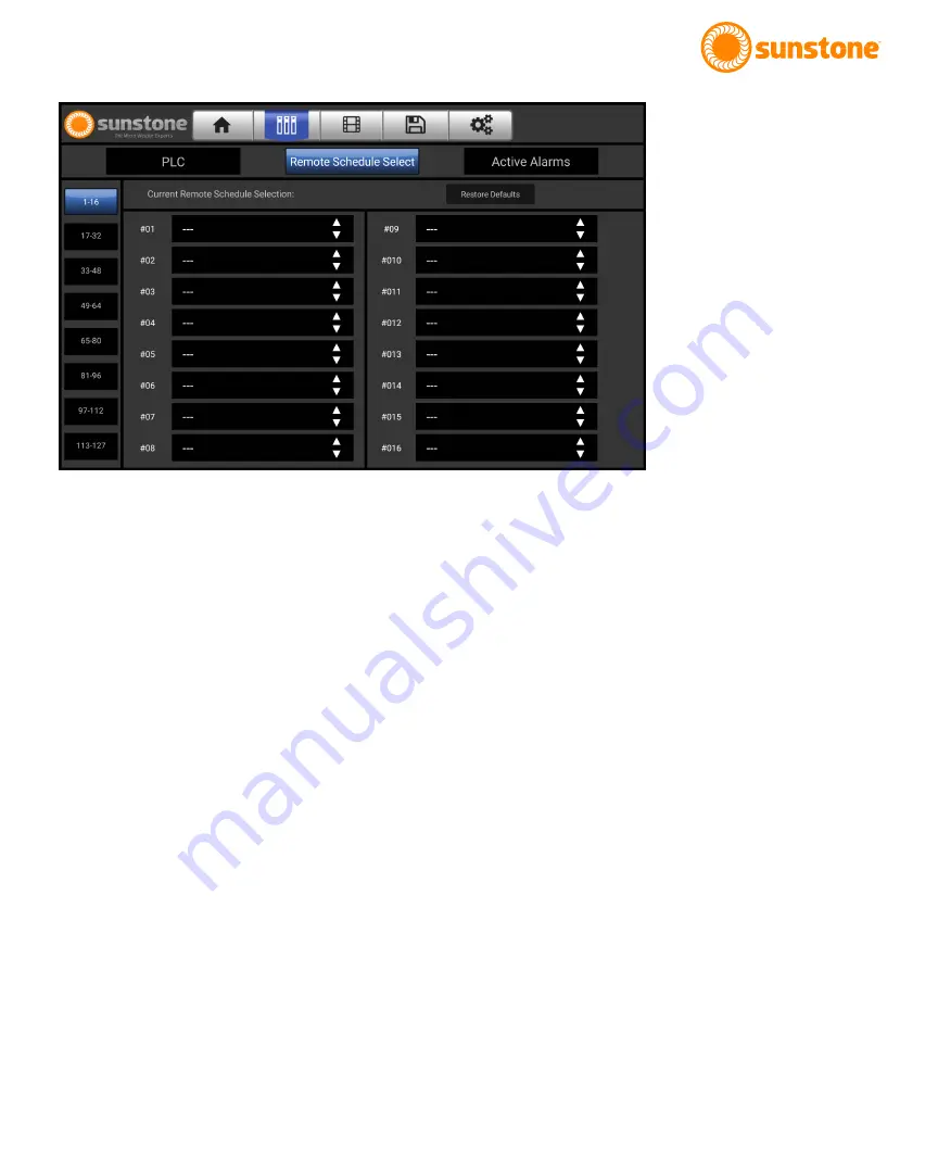
The Sunstone PA250i contains an advanced Remote Schedule Select Screen (see Figure 29.1), allowing you to 

assign up to 127 saved welds, and remotely select which one to use. Welds must be saved before they can be 

assigned on this screen (see the Save/Load Screen section on page 32 for more information on saving welds).

Assigning Saved Welds

The 127 available slots are broken up into 7 groups of 16, and 1 group of 15. Use the buttons on the left of the 

screen to select the various ranges of remote schedules, and the numbered drop downs to the right to select 

what saved weld name is assigned to that number. 

Selecting Assigned Weld Schedules

Pins 1.2 through 1.8 (refer to the Connector Pinout on page 27 for more information on pin locations) are all 

used for Remote Schedule Select. Like the PLC inputs, they too operate in active-low configurations, where a 

low value (0V) is used for selecting. These pins also have an internal limiting pull up resister to limit current.
These seven pins are bit mapped into a number between 0 and 127, with RSS 6 (pin 1.8) being the most sig-

nificant bit. The bit-mapped number will then load the corresponding Remote Schedule Select (RSS) slot. For 

example, if RSS0 (pin 1.2) and RSS1 (pin 1.3) are driven low while the rest remain high, read in as a number 

1111100, because the unit operates in an active-low configuration, and is therefore interpreted by the unit to be 

0b0000011, or slot number 3. If the RSS tries selecting a slot that does not have a weld assigned, the following 

message will appear: “Error: Invalid Remote Schedule Selection”.
When the RSS loads any numbered slot, the user interface (or UI) is locked, preventing you from changing set-

tings away from what the RSS loaded. If no pins are being driven low, the RSS is disabled, and the UI is unlocked 

so settings can be changed.

Figure 29.1. The Remote Schedule 

Select Screen allows you to save 

up to 127 different welds and select 

any one of them remotely.

Summary of Contents for OMEGA PA 250i

Page 1: ...Users Guide Version 20220405 Part 1142 250i MEGA...

Page 2: ...ING LLC PRODUCT OR LOSS OF USE OF THE SUNSTONE ENGINEERING LLC PRODUCT OR ANY THIRD PARTY PRODUCTS THAT ARE USED IN OR WITH THE SUNSTONE ENGINEERING LLC PRODUCT EVEN IF SUNSTONE ENGINEERING LLC HAS BE...

Page 3: ...ck Panel 10 Power Supply Setup Front Panel 11 Electrode Care 11 When to Sharpen the Electrode 12 Shield Gas Setup 13 Microscope LCD Shutter System 14 Omega PAWH Weld Head Setup 15 Chapter 2 User Inter...

Page 4: ...Lock Tweezers 1 Sunstone Safety Guide 1 System Cover 1 Flat Peaked Pier ACCESSORIES BOX Located in Box 2 1 Microscope Arm Mounting Hardware 1 Pair Microscope Eye Piece Shields 1 Welder Power Cord 1 Lo...

Page 5: ...ench L Attach the clamp mechanism D to the angled bracket using two 2 of the included flat head hex screws See Figure 5 2 For thicker tables attach the clamp mechanism D to the two lower holes in the...

Page 6: ...sure plate I onto the bolt Turn the adjustment knob J clockwise to tighten the plate to the underside of the table See Figure 6 3 Mounting Option 3 Screw to Table vertical surface Required hardware fr...

Page 7: ...stments Turn the hex screw counterclockwise in the direc tion of the symbol on the arm if the arm does not hold the microscope up Turn the hex screw clockwise in the direction of the symbol if the arm...

Page 8: ...ngled down Fine tune the position of the Welding Stylus while looking through the microscope Loosen the thumb screw on the bottom side of the stylus holder and slide the Welding Stylus forward and bac...

Page 9: ...easure the electrode length Place the end of the stylus hull E against the collet cap then make sure the electrode extends as indicated See Figure 9 3 There should be between 0 6 0 7 inch 1 5 2cm of t...

Page 10: ...ally sound vertical support One mounting bracket should attach to the top of the Power Supply and one to the bottom Attach the lower mounting bracket to the wall first using wood screws or other appro...

Page 11: ...r manual or CNC head follow these steps Connect the red spade connector to the Pulse Arc Port and the black spade connector to the Tack Port Plug the standard RJ12 connector to the Acc Port with the o...

Page 12: ...he diamond disc so the grit of the disk is moving parallel with the elec trode shaft and moving towards the tip See Figure 12 2 Sharpening the electrode in a way other than explained here will affect...

Page 13: ...rtant rules that should be followed when using a compressed shielding gas such as argon Always secure the pressurized gas tank to a fixed location such as a sturdy table leg If the pressurized gas cyl...

Page 14: ...electrode while looking through the microscope This is an easy challenge to overcome To begin follow the suggested practices below while the welder is in Weld Off Mode While the welder is in Weld Off...

Page 15: ...the back of the Power Supply and into the port on the back of the weld head at the bottom of the Air Valve System D See Figure 15 3 COMPLETE CABLE CONNECTIONS Plug the 4 DIN connector on the back of...

Page 16: ...he weld head as shown in Figure 16 2 Twist the electrode holder counterclockwise to open the collet Insert the electrode into the collet See Figure 16 3 Tighten the electrode holder clockwise to secur...

Page 17: ...icons located along the top of the screen in the header area Home Communications Media Save Load Settings Home Screen The Home Screen is comprised of three separate areas The Waveform Graphic Area The...

Page 18: ...e displayed along the bottom of the graph Energy discharged and weld length values are shown As length decreases the amount of energy discharged will decrease as represented in text just below the gra...

Page 19: ...text will turn orange and display Preset Loaded The button will remain in this state until settings are changed at which point it will revert to the gray Apply Preset text Waveform Drop down Use the...

Page 20: ...ate is useful for initial and daily settings setup and electrode maintenance as there is no worry for accidental welds or weld head movement Dry Run State In Dry Run the welder accepts weld triggers a...

Page 21: ...mics the weld output of a typical laser welder Ignition The Ignition options control the timing of released energy in relation to the position of the electrode Standard With this option the energy dis...

Page 22: ...ation is available for all welds with 231 Ws of energy or less Sustained The Sustained agitation option offers high levels of agitation for improved weld spot strength in some metals The high levels o...

Page 23: ...th different lengths and power settings can help achieve the best results when using Triangle and Square modes TACK CONTROL LAYOUT The Sunstone Omega PA250i is capable of performing resistance tack we...

Page 24: ...mode When this button is selected the Pedal Button will be grayed out Foot Pedal When Foot Pedal is selected the welder will only initiate when the foot pedal is pressed Move the grounded workpiece in...

Page 25: ...r rough surfaces or if weld spots are close together Agitation Options Adjust the agitation frequency duty cycle and weld percentage Gas Options View gas pressure gauge and adjust gas flow timing Tapp...

Page 26: ...A short description will appear for various buttons sliders when they are in use Keypad Mode The numbered keypad will stay visible when this mode is selected Weld Counters View and reset weld counter...

Page 27: ...not stuck to the work piece They will remain low 0V until a weld is attempted or until you set a new energy value If in Weld Head mode Weld Ready will also depend on whether the weld head is connected...

Page 28: ...ode is stuck to the workpiece and will stay low until the workpiece and electrode are separated This is a critical error when automating the welder as trying to move a stuck electrode can cause damage...

Page 29: ...ctive low configurations where a low value 0V is used for selecting These pins also have an internal limiting pull up resister to limit current These seven pins are bit mapped into a number between 0...

Page 30: ...n Sunstone has also programmed in critical temperature value thresholds where the fans will turn on regardless of alarm status and in event of critically high temperatures welding will be disabled Onc...

Page 31: ...eloaded media that can be viewed from the Media Screen for help and information regarding welding see Figure 31 1 The Users Manual can also be found here Press on the desired drop down box on the left...

Page 32: ...ick the Save as New Button This stores the file for retrieval at a later date The saved file will appear in the column on the left Click the Save Button to save the current settings over another alrea...

Page 33: ...the microscope Screen Brightness Slider Adjust the brightness of the screen as desired Language Selection Drop Down Box The Sunstone PA250i comes preloaded with several language options Press the down...

Page 34: ...nt metals may require different values Higher frequencies will help break up crystalline structures during cooling Duty Cycle Slider Higher duty cycle means more spikes will occur during the weld and...

Page 35: ...rge Gas Button Allows you to purge the line of air and or gas useful for pressurization and to check gas flow TIMING OPTIONS Each slider has and buttons that will appear for five seconds after the sli...

Page 36: ...801 658 0015 User Manual 250i MEGA Figure 36 1 Touch the Timing Button to adjust various system timings Figure 36 2 Touch the Systems Button to restore defaults update the welder s software clear memo...

Page 37: ...u to update the system from the Sunstone server via WiFi Enter Test Suite This button is for Sunstone Tech Support diagnostics and requires a password to enter Hardware Revision Displays the revision...

Page 38: ...updates via email As Sunstone develops new software with more efficient settings and or features to provide the very best welding experience these updates will be available on the Sunstone website for...

Page 39: ...lete Update via WiFi Go to the Settings Screen by pressing the gears icon on the top right of the screen Press the System Button and press the Update Over WiFi Button this will update the welder to th...

Page 40: ...ip firmly to the corner of the provided stainless steel weld plate or other practice material On the Home Screen Click the ARC tab to bring up the options see Figure 41 1 Select Classic waveform Selec...

Page 41: ...tylus and the effects of different weld parameters Ensure the weld cable has a resistance of at least 20m when using an arc cable not supplied by Sunstone MAKE A TACK WELD For more information on Tack...

Page 42: ...factors can influence the way the welder will behave for any given combination of settings i e types of metal being used thickness of metal geometry of the workpieces gaps between mating surfaces elec...

Page 43: ...prior to the weld can have a large influence on weld quality and behavior Knowing the correct angle of approach and the correct place to touch the electrode can lead to more consistent weld results an...

Page 44: ...WELD DISCHARGE WAVEFORM The shape of the waveform indicates the way the energy is being discharged Classic Mode has a high peak current which drops more quickly than the other two waveforms leading to...

Page 45: ...e weld quality in certain metals like stainless steel Negative agitation takes energy away from the total amount of energy Length The length of the weld discharge is a large part of how much energy is...

Page 46: ...Description Electromagnetic Compatibility EMC 2014 20 EU Council Directive 2014 30 EU February 26 2014 on Electromagnetic Compatibility Low Voltage Directive LVD 2014 35 EU Council Directive 2014 35...

Page 47: ...unstone CDDP A line of fine spot resistance welders is no exception A touchscreen interface lets you adjust power by 1 100th of a Ws Plus you have full control over the wavelength With absolute energy...

Page 48: ...Ste 5 Payson UT 84651 USA Tel 1 801 658 0015 wwww sunstonewelders com 2022 Sunstone Engineering LLC Safety information subject to change Sunstone and Orion are trademarks of Sunstone Engineering LLC 2...

Reviews: