42. Center Truing Sleeve over stone and shoes.
43. Grasp Workholding Fixture and Truing Sleeve
firmly and depress Pedal slowly.
CAUTION
Always release Pedal before removing Truing Sleeve
from mandrel.
44. As mandrel begins its rotation, stroke Truing
Sleeve forward and back. Use short strokes at first,
then gradually lengthen stroke until stroke length is
about as long as stone or Truing Sleeve, whichever
is longer. Reverse Truing Sleeve frequently.
If Truing Sleeve is too hard to hold or Honing Dial
Needle moves too rapidly, reduce cutting pressure.
Honing Dial Needle does not move or moves too
slowly, increase cutting pressure.
45. As soon as the truing sleeve and stone become
saturated with oil, adjust Total Volume Control
Valve so that the oil no longer reaches the mandrel
or truing sleeve.
The coolant on Truing Sleeve and stone create a
lapping paste as you are honing; as paste dries out,
add a small amount of Coolant.
Always hone workpiece most where you feel most
pull or resistance.
46. When Honing Dial Needle reaches "0", release
Pedal.
47. Advance Feed Dial four (4) numbers; Depress
Pedal and continue honing until Honing Dial Needle
reaches "0"; then release Pedal.
CAUTION
Always release Pedal before removing Truing Sleeve
from mandrel.
48. Reverse Truing Sleeve frequently. After revers-
ing Truing Sleeve several times stop and examine
stone and shoes.
NOTE:
High spots on stones will be loaded (
see
Figure 2-16
). Use the LBN-700 Abrasive Stick to
remove high spots on stone. High spots on shoe will
be bright and shiny. A few light strokes with a file
will remove these high spots (use an abrasive stick
like the LBN-700 to true hardened steel guide shoes).
49. Repeat above operation, until at least a line contact
is achieved on each shoe and on stone.
NOTE:
The objective of truing the mandrel and stone
is to make the shoes and stones parallel. However,
when honing to very close tolerances or when honing
holes with keyways, the honing unit should also be
trued to the finish bore diameter as closely as possible.
When truing Keyway (Y-type) mandrels, refer to
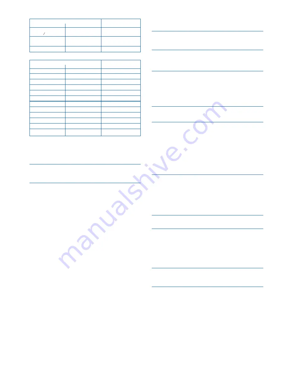
instruction sheet packed with mandrel. Keyway
mandrels should be fully radiused to within .005"
(0.13 mm) of workpiece finish bore size.
50. When mandrel is trued in, push STOP Button.
51. Replace Spindle Cover.
SPINDLE SPEED
52. Open Belt Guard, by loosening Safety Latch Pin
and raising Belt Cover Latch.
NOTE:
Turn Disconnect Switch on left side of Belt
Guard to OFF position, then open doors.
53. Using Chart on inside of Belt Guard, select Spindle
Speed according to bore diameter
(see Table 2-5)
.
If the part is heavy enough to exert a considerable
force on honing unit/mandrel, use a slower speed
than shown. For external honing, use two speeds
slower than shown
CAUTION
Extra long mandrels should be run at a slower speed
than shown.
54. With motor OFF, pull Idler Handle down.
55. Move V-Belt to appropriate groove. Use 320 rpm
for most passenger car and light truck rods in 1.4 to
2.6 in (36-66 mm) diameter range. Use 250 rpm for
large truck rods over 2.6 in (66 mm) in diameter.
11
TABLE 2-4, Cutting Pressure Setting
BORE SIZE
PRESSURE CONTROL
inches
millimeters
INITIAL SETTING
.375 to .500
9,5 to 12,7
1
(
3 8
to ½)
.500 to 1.000
12,7 to 25,4
1-½
(½ to 1)
1.000 UP
25,4 UP
2
TABLE 2-5, Spindle Speed Selection
WORK DIAMETER
SPINDLE
inches
millimeters
SPEED
UNDER 1.250
UNDER 32
640
1.250-1.625
32-41
500
1.625 - 2.000
41-51
400
2.000 - 2.500
51-64
320
2.500 - 3.250
64-83
250
OVER 3.250
OVER 18
200
UNDER .500
UNDER 13
640
.750
18
500
.875
22
400
1.000
25
320
1.500
38
250
OVER 2.000
OVER 51
200
CAUTION: Power MUST be OFF when Guard is open.
Summary of Contents for LBB-1660
Page 8: ...NOTES viii...
Page 34: ...NOTES 26...
Page 38: ...NOTES 30...
Page 40: ...NOTES 32...
Page 44: ...NOTES 36...
Page 45: ...37 APPENDIX E DECLARATION OF CONFORMITY CE PAGE 1 OF 2 SAMPLE CE DOCUMENT...
Page 46: ...38 APPENDIX E DECLARATION OF CONFORMITY CE PAGE 2 OF 2 SAMPLE CE DOCUMENT...


