background image

11. Rotate Light Cutting Pressure Control all the
way counterclockwise against stop (to zero).

12. Turn Threaded Sleeve (B) clockwise (as viewed
from rear of machine) until light pressure control
fork will not return to contact collar when it is
pulled away

(refer to Figure 4-5)

.

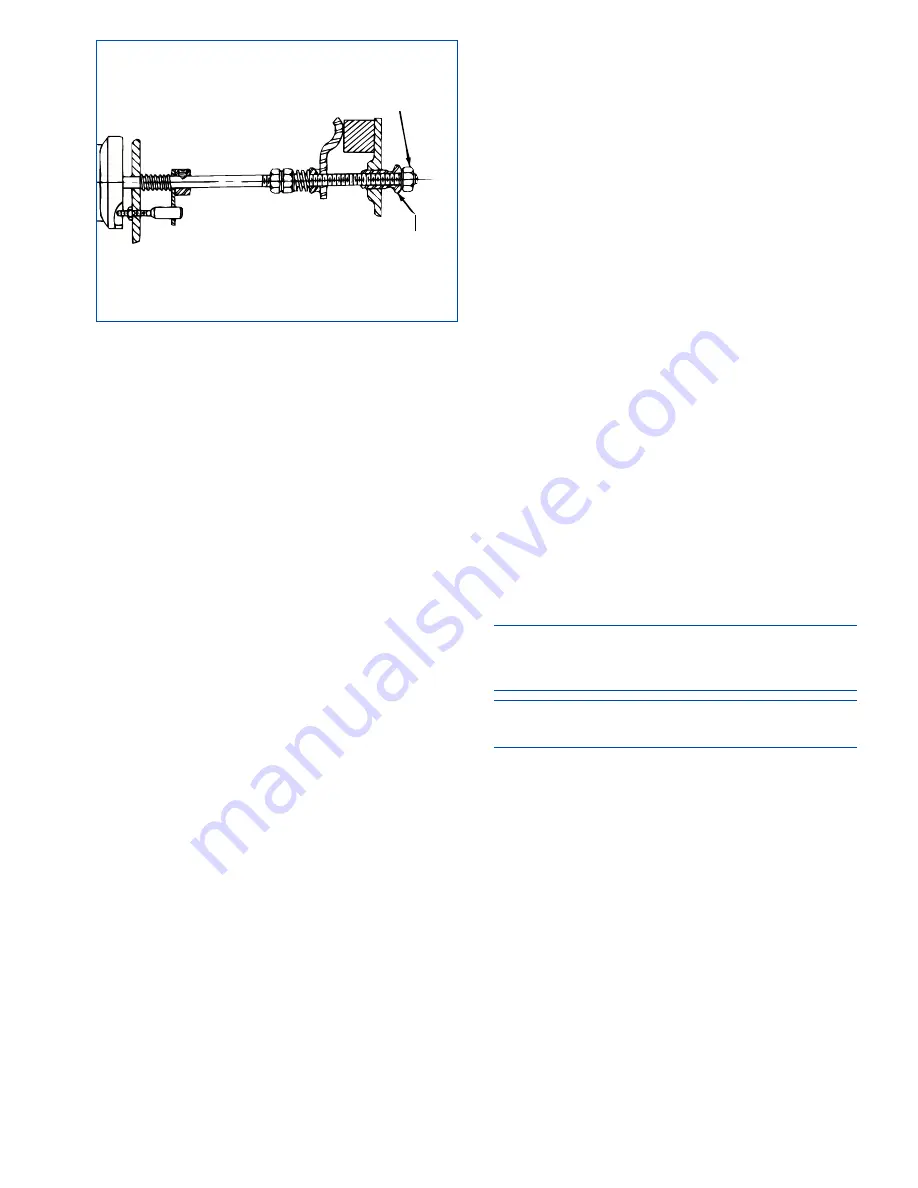
13. Loosen Locknut (C) on Heavy Cutting Pressure
Control shaft 

(see Figure 4-9)

.

14. Rotate Heavy Cutting Pressure Control all the
way counterclockwise against stop (to zero).

15. Turn Threaded Sleeve (D) clockwise (as viewed
from rear of machine) until honing dial needle will
not return to zero when Feed Dial is pushed all the
way in and slowly released.

16. Set Heavy Cutting Pressure Control so that
handle is in line with upper surface of spindle nose

(refer to Figure 4-6)

.

17. Push Feed Dial in as far as you can and release
slowly.

18. While holding Heavy Cutting Pressure Control
in position set in step 21, watch Honing Dial and
turn threaded sleeve D counterclockwise slowly
until honing dial needle moves to between 4 and 5.
If honing dial needle suddenly moves to red line, stop
adjusting threaded sleeve D. Push in on Feed Dial
again and release slowly. If needle stops between 
4 and 5, adjustment of threaded sleeve D is correct.
If needle still moves quickly to red line, turn threaded
sleeve D clockwise a small amount and again push
Feed Dial in and release slowly.
Continue adjusting threaded sleeve D until needle
stops between 4 and 5 when Feed Dial is pushed are
released slowly.

19. Tighten locknut C against threaded sleeve D.

20. Recheck threaded sleeve D adjustment by pushing
Feed Dial in as far you can and releasing slowly . . .

honing dial needle should stop between 4 and 5. If
it doesn't, loosen locknut C and repeat step 18.

21. Make sure both pressure controls are turned all
the way counterclockwise against stops (to zero).

22. Push Feed Dial in as far as you can and release
slowly.

23. While holding light cutting pressure control
against stop (at zero) watch honing dial and turn
Threaded Sleeve B slowly counterclockwise until
the needle moves to between 8 and +1 

(refer to

Figure 4-8)

.

If needle suddenly moves past 8 toward red line,
stop adjusting Threaded Sleeve B. Push in on Feed
Dial again and release slowly.
If honing dial needle stops between 8 and +1,
adjustment of Threaded Sleeve B is correct. If honing
dial needle still moves quickly past 8 toward red area,
turn Threaded Sleeve B clockwise, a. small amount
and again push Feed, Dial in and release slowly.
Continue adjusting Threaded Sleeve B until needle
stops between 8 and +11 when Feed Dial is pushed
in and released slowly.

24. Tighten Locknut A against Sleeve B. Approximate
adjustment of Light Pressure Control is now complete.

8. Set Heavy Cutting Pressure Control to zero.

9. Set Light Cutting Pressure Control to zero.

10. Check light pressure control fork to make sure it
is seated on shoulder of collar

(refer to Figure 4-5)

.

IMPORTANT

Turn machine ON but do not run spindle while Steps
11 and 12 are performed.

CAUTION

Belt guard must be closed when motor is on.

11. Push Feed Dial in. Slowly release. Honing dial
needle should move toward red line and stop
between 0 and 2, or just barely continue to move.

12. Rotate Light Cutting Pressure Control to 1/2.
Honing dial needle should move to red line.
If everything is okay, continue with step 8.
If not, skip to step 13.

25. Recheck Light Cutting Pressure Control (Sleeve
B) as instructed in steps 8-12.
If the honing dial needle moves quickly to the red
line in Step b.(5). push the Stop button and allow
motor to stop. Open belt guard. Loosen Locknut A
and turn Sleeve B clock-wise a small amount.
Tighten Locknut A against Sleeve B.

Recheck Sleeve B adjustment as necessary using the
procedure in Step (18) above.

21

FIGURE 4-9, Heavy Cutting Pressure Control

LOCKNUT

(C)

THREADED

SLEEVE (D)

Summary of Contents for LBB-1660

Page 1: ...HE FOLLOWING INSTRUCTIONS THOROUGHLYAND CAREFULLY BEFORE UNPACKING INSPECTING OR INSTALLING THE SUNNEN HONING MACHINE I LBB 661H Installation Setup and Operation INSTRUCTIONS for SUNNEN HONING MACHINE...

Page 2: ...y optional devices equipment between the Drive motor output chokes etc For fast service on your orders call Sunnen Automotive Customer Service toll free at 1 800 772 2878 Sunnen Industrial Customer Se...

Page 3: ...DY THEREFORE SHALL IN ALL EVENTS BE LIMITED IN AMOUNT TO THE PURCHASE PRICE OF THAT PORTION OF THE PRODUCTS WITH RESPECT TO WHICH A VALID CLAIM IS MADE Shipping Damages Except in the case of F O B Buy...

Page 4: ...tructions before attempting to use this machine Always disconnect power at main enclosure before servicing machine 1 Always wear eye protection when operating this machine WARNING Do not wear cotton o...

Page 5: ...13 Operation 15 ROUTINE MAINTENANCE 17 General 17 Cleaning 17 Lubrication 17 Coolant Lines Check 17 Coolant Level Check 18 Sediment Tray 18 Coolant Reservoir 18 Feed Dial 19 Honing Dial 19 Cutting Pre...

Page 6: ...n Honing Machine When ordering parts for or requesting information about your Machine include model and serial numbers located on Electrical Enclosure of your Machine As there are numerous workpieces...

Page 7: ...739 kg sm 151 lbs sf 152 mm 6 in WITH DOOR OPEN 1524 mm 60 in WITH PAN EXTENDED 1054 mm 41 5 in WITH PAN RETRACTED 813 mm 32 in 730 mm 28 75 in 700 mm 27 5 in 6 5 mm 0 25 in 1600 mm 63 in FRONT 587 4...

Page 8: ...NOTES viii...

Page 9: ...er 4 Place Machine in desired location 5 Level Machine in both left to right and front to back directions Shim as required NOTE For permanent installation secure Machine s Support Feet to Floor with F...

Page 10: ...r appropriate personal protective equipment Follow proper lockout tagout procedures Failure to comply can result in death or injury CAUTION Do not modify plug provided on single phase machines if it w...

Page 11: ...sonal fall hazard OPERATIONAL CHECK Read Section 2 and 3 thoroughly and carefully before performing Operational Check 1 Turn ON power at Main Power Disconnect 2 Direct Coolant Nozzles downward toward...

Page 12: ...be used to shut entire supply off leaving individual settings unchanged FIGURE 2 1 Major Components CONTROLS WORK TRAY Optional GAGE Optional WORK TRAY Optional MOVABLE TRAY ACCESS DOOR PEDAL ASSEMBL...

Page 13: ...embly starts spindle drive motor stroking drive motor and expands stones Assembly consist of following components Adjustable Pedal Bar Pedal is located on lower front of machine Both Bar and Pedal are...

Page 14: ...eliminating readjustment of individual coolant nozzle control valve setting Coolant Nozzles attaches to Coolant Support Arm located on front of machine in Movable Tray Nozzles supply coolant to workp...

Page 15: ...Expands or retracts stones in honing tools Setting on Rotatory dial indicates amount of stone feed per dial graduation Dial for various tools See Stone Expansion Chart Honing Dial Indicates amount of...

Page 16: ...a fine stone for finishing Always use the coarsest stone that will produce an acceptable surface finish Short open bores blind bores and tandem bores may require minor alterations of standard stones 5...

Page 17: ...Light Cutting Pressure Control to 1 and set Heavy Cutting Pressure Control to 0 23 Turn Feed Dial counterclockwise to end of range MANDREL RUNOUT NOTE CR Series of Honing Units do not require mandrel...

Page 18: ...one parallel to mandrel Adjust Total Volume and Individual Control Valves 33 Press STOP Button 34 Set Light Cutting Pressure Control according to Table 2 4 or Your Sunnen SMOPS Guide see Figure 2 15 N...

Page 19: ...until at least a line contact is achieved on each shoe and on stone NOTE The objective of truing the mandrel and stone is to make the shoes and stones parallel However when honing to very close toler...

Page 20: ...art or holding fixture will allow Position Work Support as close as possible to end of Rod without locating on curved portion of rod CAUTION All workpieces MUST be in a Holding Fixture to avoid injury...

Page 21: ...ing of Electrical Components Clear area of excessive lubricant or lubricant spills Coolant can be slick DO NOT adjust stroke length while honing KEEP hands clear of all moving parts Stay clear of all...

Page 22: ...stop stroking in middle of stone Use a con rod type hone unit Set Heavy Cutting Pressure Dial to 0 For rough honing set Light Cutting Pressure Dial between 2 1 2 to 3 and for finish honing set Light...

Page 23: ...s Direct coolant stream onto both ends of honing unit so flow of coolant will enter bore being honed see Figure 3 5 Use a continuous and ample supply of Sunnen Industrial Honing Oil to ensure accurate...

Page 24: ...allows part to be honed in one opera tion without having to gage and hone each part sev eral times until it is to size When parts vary widely in amount of stock to be removed you can NOT estimate how...

Page 25: ...tween lubrication will vary with amount of use your Machine receives Lubricate all components at least once every six months CAUTION Be careful not to get oil on drive belts pulleys or brake strap Oil...

Page 26: ...g power 1 Turn OFF all electrical power to machine 2 Open Access Door on front of machine 3 Push Drain Pipe up to left 4 Grasp Sediment Tray lip which over hangs right side of Reservoir and tip tray t...

Page 27: ...ement Tray 28 Pull Drain Pipe down and to right 29 Direct Coolant Nozzles into Work Tray and close Total Volume Control Valve 30 Close Door on front of machine 31 Dispose of coolant and sludge accordi...

Page 28: ...ure 4 5 NOTE Turn Disconnect Switch on left side of Belt Guard to OFF position then open doors 2 Rotate Feed Dial all of the way in either direction then back off six turns 3 Set Heavy Cutting Pressur...

Page 29: ...gainst stops to zero 22 Push Feed Dial in as far as you can and release slowly 23 While holding light cutting pressure control against stop at zero watch honing dial and turn Threaded Sleeve B slowly...

Page 30: ...belt it should be just tight enough to turn the oil pump pulley without slipping If oil pressure falls excessively when spindle rotates oil pump belt may be too loose TO ADJUST the oil pump belt make...

Page 31: ...lose and secure belt guard 9 Turn ON power ADJUST SPINDLE DRIVE BELT To check flat spindle drive belt adjustment tension should be such that with motor ON spindle starts rotating an instant after the...

Page 32: ...Rod by engaging Adjusting Nut Assembly with Feed Screw and turning Feed Dial clockwise while inserting Feed Rod into Thrust Assembly Projection on Adjusting Nut Assembly must point upward Bearing reta...

Page 33: ...ve Slotted Head Screw C and Washer from Brake Cam Discard worn Brake Strap refer to Figure 4 18 9 Clean groove in which strap rides on Spindle Pulley CAUTION Brake Strap must be positioned on Brake Ca...

Page 34: ...NOTES 26...

Page 35: ...ncrease cutting pressure Dial Needle 3 Improper stone A Use softer stone moves too slowly B Use coarser stone 4 Improper or diluted coolant A Check coolant 4 Poor stone life 1 Excessive stone feed up...

Page 36: ...stone length A Use mandrel with sufficient stone length to bridge waviness in bore Rainbow 1 Improper mandrel A Use L BL or multi stone mandrel stone length should be 1 1 2 times bore length 2 Improp...

Page 37: ...workpiece in a Workholding Fixture and use Work Support at all times o 22 Install part in workholding fixture o 23 Slide part and fixture on mandrel o 24 Depress Pedal o 25 Adjust Feed Dial for stock...

Page 38: ...NOTES 30...

Page 39: ...ce 0 018 to 0 023 Free Side Free Side clearance PRECISION PIN FITS ON ENGINES WITH 32 to 38 mm DIAMETER PINS DIAMETER ALUMINUM PISTON CAST IRON PISTON CONNECTING RODS FULL 0 018 to 0 023 clearance FLO...

Page 40: ...NOTES 32...

Page 41: ...50 18 1 to 19 0 4ML 718M 713 to 750 18 1 to 19 0 4ML 750M 744 to 781 18 9 to 19 8 4ML 781M 775 to 815 19 7 to 20 7 4ML 812M 806 to 843 20 5 to 21 4 4ML 843M 838 to 875 21 3 to 22 2 5ML 875M 869 to 906...

Page 42: ...7 KL 775M 775 to 805 19 7 to 20 4 KL 806m 806 to 837 20 5 to 21 3 KL 838M 838 to 868 21 3 to 22 0 KL 869M 869 to 899 22 1 to 22 8 KL 900M 900 to 930 22 1 to 23 6 KL 931M 931 to 961 23 6 to 24 4 KL 962...

Page 43: ...35 APPENDIX D COOLANT FLOW DIAGRAM PUMP CHECK VALVE MACHINE RESERVOIR DIRTY OIL DIRTY OIL DIRTY OIL MANIFOLD TRAY FIGURE D 1 Coolant Flow Diagram CLAMP KNOB PUMP BRACKET PUMP SCREEN...

Page 44: ...NOTES 36...

Page 45: ...37 APPENDIX E DECLARATION OF CONFORMITY CE PAGE 1 OF 2 SAMPLE CE DOCUMENT...

Page 46: ...38 APPENDIX E DECLARATION OF CONFORMITY CE PAGE 2 OF 2 SAMPLE CE DOCUMENT...

Page 47: ...ly Be sure to read and follow instructions for operation of equipment WARNING An Arc Flash Hazard Exists Follow safe work practices and wear appropriate Personal Protective Equipment Follow proper loc...

Page 48: ...25 4000 1 1 16 1 062500 26 9880 FORMULAS MULTIPLY BY TO GET MULTIPLY BY TO GET INCHES in x 25 4 MILLIMETERS mm MILLIMETERS mm x 0 03937 INCHES in FEET ft x 0 3048 METERS m METERS m x 3 281 FEET ft PR...

Reviews: