background image


56 Broome Corporate Parkway 
Conklin, NY 13748 USA                 
P 877.786.6299 | F 877.786.0329 


www.sunmaxxsolar.com 

Page 2 of 47 


Contents 


IMPORTANT INFORMATION AND WARNINGS ........................................................................ 3 

SOLAR WATER HEATER PACK AND TRANSPORT .................................................................. 4 

1. Features of pressurized solar water heater .................................................................................... 5 

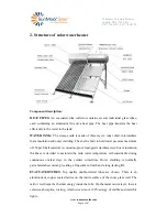
2. Structure of solar water heater ...................................................................................................... 6 

3. Working principle .......................................................................................................................... 7 

3.1. Principle of vacuum tube ................................................................................................... 7 

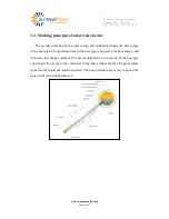
3.2. Working principle of solar water heater ............................................................................. 8 

4. Technical data and product description ......................................................................................... 9 

4.1 Technical data ...................................................................................................................... 9 

4.2 System Tolerance Information .......................................................................................... 10 

4.3 System start-up procedures ............................................................................................... 10 

4.4 System pipe anti-freezing protections ............................................................................... 11 

4.5 Specific notices ................................................................................................................. 12 

5. Installation of solar water heater ................................................................................................. 14 

5.1. Frame installation drawing ............................................................................................... 14 

5.2. Water tank and vacuum tube assembly drawing .............................................................. 15 

5.3. Solar water heater assembly step ..................................................................................... 15 

6. Pipeline installation ..................................................................................................................... 24 

6.1 plumbing system schematic map....................................................................................... 24 

6.2 plumbing connections ....................................................................................................... 29 

        All the system labels will be packaged with the product when shipment and all of them were 

        made of weather proof material. Some of them must be attached to the valves with plastic or 

        wire tie after installation. If the label is lost or damaged for some reason, type a new one on 

        heavy paper stock and seal in clear plastic to make it water proof. ........................................31 

6.3 Insulate the pipe ................................................................................................................ 34 

7. Commissioning the system ......................................................................................................... 37 

8. Troubleshooting .......................................................................................................................... 38 

9. Maintenance requirements .......................................................................................................... 39 

9.1. Cleaning ........................................................................................................................... 39 

9.2. Leaves .............................................................................................................................. 39 

9.3. Broken tube ...................................................................................................................... 39 

10. Special conditional operation .................................................................................................... 40 

11. Other important information ..................................................................................................... 41 

12. Warranty Card ........................................................................................................................... 41 

For you record: ................................................................................................................................ 42 

ANNEX 1. ....................................................................................................................................... 43 

ANNEX 2 Notice Label .................................................................................................................. 46 


Summary of Contents for ThermoPower-VTS30-HP Series

Page 1: ...manual applies to Model ThermoPower VTS30HP The solar energy system described by this manual when properly installed and maintained meets the minimum standards established by the SRCC This certificati...

Page 2: ...tion drawing 14 5 2 Water tank and vacuum tube assembly drawing 15 5 3 Solar water heater assembly step 15 6 Pipeline installation 24 6 1 plumbing system schematic map 24 6 2 plumbing connections 29 A...

Page 3: ...ed and maintained in accordance with the manufacturers instructions Children should be supervised to ensure they DO NOT play with the appliance Prevent from burn injury touching the heat pipes in the...

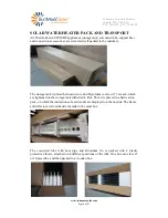
Page 4: ...e tank is placed between two round Styrofoam covers of 7 cm each which are tightened on the storage tank with stretch film Then it is placed in a hard carton pack on which the indications of each mode...

Page 5: ...put during the sun s highest energy around midday Utilization all year round even in cold windy climates where freezing does not occur below 2 degrees Celsius for short periods of time Can operate wit...

Page 6: ...lt to hold water pressure maximum of 150psi Shell material is corrosion proof food grade stainless steel Foam insulation thickness is decided to maintain the tank water temperature self sustainable du...

Page 7: ...nel The reflectors can improve solar system thermal efficiency and reinforce the frame structure FRAMES Frame is made of rustproof material Aframe may have full length rear legs suitable for flat surf...

Page 8: ...luminum fin pass the heat energy to the heat pipe The liquid medium in the heat pipe is heated by the heat energy and then turns into the gas medium The gas medium flows up to the top of the heat pipe...

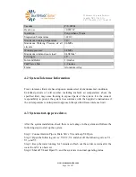
Page 9: ...echnical data and product description 4 1 Technical data Model ThermoPower VTS30HP Number of Tubes 30 Gross area 4 45m2 Tank Volumetric Capacity 300L Weight Empty 90Kg Fill weight 330Kg Length of Tube...

Page 10: ...ambient air temperatures above the specified limit may cause freezing in exposed parts of the system It is the owner s responsibility to protect the system in accordance with the Supplier s instructio...

Page 11: ...e connecting pipe freezing The connecting pipe can be protected against freeze damage In case of black out or power outage occurs during the cold weather when the temperature is lower than 14 Fahrenhe...

Page 12: ...de the heat pipe GUIDE 6 1 3 6 and 6 3 7 The HTF inside the heat pipe is a small amount of pure water at a very low pressure The heat pipe HTF are built as one unit no refill is needed and the water i...

Page 13: ...5 10 System mounting GUIDE 6 5 12 6 5 13 6 5 14 and 6 5 19 Allocate a place is not shaded during 10 00AM to 3 00PM and keep the solar panel facing south with 45 degrees of adjustment tolerance The pit...

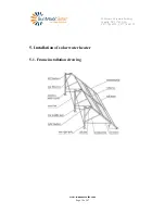
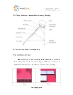
Page 14: ...56 Broome Corporate Parkway Conklin NY 13748 USA P 877 786 6299 F 877 786 0329 www sunmaxxsolar com Page 14 of 47 5 Installation of solar water heater 5 1 Frame installation drawing...

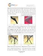
Page 15: ...m tube assembly drawing 5 3 Solar water heater assembly step 5 3 1 Installation of frame Firstly open the packing case to check the fittings related with the frames and their quantity They include fro...

Page 16: ...allation of the rear legs and assistant bars Fig 3 Fig 4 Step 3 Find the tank brackets and connect them with rear legs Attention The installation of the three tank brackets is the key point observe ca...

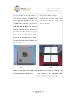
Page 17: ...the reflectors by the same screw Take the last rear leg out and connect it with the tank brackets Then use the assistant bars to connect the rear and front legs in the same way mentioned above with th...

Page 18: ...the water tank into the corresponding connecting holes of the tank brackets Step 2 Install the accessories and revolve the small red cap of the air vent on the top to ventilate Step 3 Install the T P...

Page 19: ...tightly by 22mm spanner Please pay attention to the tightness extent avoiding being too loose to cause water leakage Step 7 Install all the heat pipes according to this method Adjust the angle and the...

Page 20: ...provide accurate compass headings and your exact latitude If you do not have a compass or GPS wait until solar noon and the shadow of a vertical stick or surface will point due North True South is 18...

Page 21: ...Portland OR Minneapolis MN Bangor ME 45 Buffalo NY 43 Chicago IL Boston MA Detroit MI 42 Denver CO Indianapolis IN Philadelphia PA 40 Kansas City MO St Louis MO Washington DC Cincinnati OH 39 Reno NV...

Page 22: ...operations to prevent from injury during installation o The solar water heater must be installed in locations with wind and snow load lower than 0 49kN m If the wind and snow load in the locations mo...

Page 23: ...nt must connect the roof conductive part to the ground wire with at least 16 mm grounding cables For building height installation height less than 20 meters do not need to adopt the special measures t...

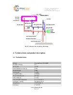
Page 24: ...F and 130 psig As the thermosiphon system has no way to stop the operation of the solar collector always install a TP R valve to release some high temperature water out of the tank then mains water wi...

Page 25: ...no less than 2 cm vertical drop for each meter of horizontal length 1 4 inch per foot The illustration is the installation pipe line of pressurized solar water heater The directions of each valve and...

Page 26: ...e wire can meet the heat element maximum power The above is a reference plumbing connection diagram The formal plumbing architecture design and blueprint drawing shall always be done by a licensed arc...

Page 27: ...emperature sensor into the inlet and outlet pipe Method 1 use a three way valve and sensor pocket to install the temperature sensor at the inlet and outlet port of the water tank Fig1 sensor pocket Fi...

Page 28: ...refer the monitor diagram below To determine whether the solar system is working observe the thermometer when the hot water is being used in the house The water returning from the collector on a sunn...

Page 29: ...877 786 6299 F 877 786 0329 www sunmaxxsolar com Page 29 of 47 6 2 plumbing connections Components list and Valve labels ID Name Normal operation position Model technical specification Photo Quantity...

Page 30: ...Drains hose outlet connection with NPT threaded inlets 1 V5 Solar Drain valve OFF 3 4 Drains hose outlet connection with NPT threaded inlets 1 V6 Mixing valve Set temperature 48 9oC 1 2 WATTS series...

Page 31: ...3 4 Materials shall meet the standards of the national sanitation foundation Connection 2 3 4 CxCxC Tee and Couplings Cooper 3 4 Materials shall meet the standards of the national sanitation foundatio...

Page 32: ...eration position OPEN City water shut off valve OPEN V0 Connection 3 3 4 Copper x Female Adapter Cooper 3 4 Materials shall meet the standards of the national sanitation foundation Connection 4 3 4 x...

Page 33: ...fluid identity and AWWA class 1 warning that fluid may be discharged at high temperature and or pressure Unauthorized alterations to this system could result in a hazardous health condition Solar Isol...

Page 34: ...the system as conceal pipe any economic losses caused by the leakage of conceal pipe and other related reasons shall not be borne by our company If insulation is required the full length of the solar...

Page 35: ...y good on higher pipes that reach greater temperatures like steam pipes where the additional heat levels can damage the foam tubing While they are an option for cold water pipes it would be better to...

Page 36: ...ulation jackets or a coating of exterior grade latex paint or metal tape is recommended Do not uses duct tape because it will quickly deteriorate when exposed to outdoor conditions The drain plugs on...

Page 37: ...e V4 and keep V4 Open Step 2 Open the following valves V0 V2 V4 and shut off the following valves V1 V3 and V5 Step 3 Keep the water running for 5 minutes to flash out the solder or stains after the w...

Page 38: ...the heat pipe and daub some silicon grease on the heat pipe s condenser then reinsert it into the manifold d Pipe line does not seal and is no insulated very well so there is more energy loss Check a...

Page 39: ...eplaced as soon as possible to maintain maximum collector performance The system will still operate normally even with a tube broken Any broken glass should be cleared away to prevent injury To replac...

Page 40: ...ssure is high please turn down the filling water valve so cold water can enter into the water tank slowly 4 Collector should be mirror like or else it means tube is not in the vacuum condition If it a...

Page 41: ...er installing 12 Warranty Card Upon installation of the solar system the dealer responsible for the sale will fill out the warranty card and the customer will complete a record of it and retain it for...

Page 42: ...stem Costs associated with the replacement and repair of the unit including freight shipping or delivery charges removal installation or re installation charges any material and permits required for i...

Page 43: ...nd aluminum 30 2 7 Tank 1 3 T P relief valve 1 4 Automatic air vent 1 5 6 Sealing gasket 30 6 5 Heat pipe screw 30 7 8 Tank support 4 8 9 Acclivitous support 4 9 10 Back leg 2 10 11 Inclined support 4...

Page 44: ...56 Broome Corporate Parkway Conklin NY 13748 USA P 877 786 6299 F 877 786 0329 www sunmaxxsolar com Page 44 of 47...

Page 45: ...perature monitor 1 25 TEE Coupling 3 4 Per the actual install conditions 26 Pipe insulation 2 Per the actual install conditions 27 Pipe insulation 3 4 Per the actual install conditions 28 PVC pipe 4 P...

Page 46: ...r com Page 46 of 47 ANNEX 2 Notice Label Hot warning label Freeze protection label Freeze Protection Information The freeze protection method of this system is thermal mass and manual draining Drain t...

Page 47: ...rmoPower VTS30HP Aperture area 2 84 m2 Nominal capacity of the storage vessel 63 gal Max Operating Pressure 87 psi Max Operating Temperature 194o F Collector transfer medium water antifreeze no toxic...

Reviews: