background image

______________________________SULLIVAN-PALATEK 

TABLE OF CONTENTS 

SECTION 1 - SAFETY .......................................................................................... 4


1.1


GENERAL ........................................................................................................... 4


1.2


PRESSURE RELEASE ...................................................................................... 4


1.3


FIRES/EXPLOSIONS ......................................................................................... 5


1.4


MOVING PARTS ................................................................................................ 5


1.5


PHYSICAL DANGERS ....................................................................................... 6


1.6


TOXICITY ........................................................................................................... 6


1.7


ELECTRIC SHOCK ............................................................................................ 6


1.8


LIFTING .............................................................................................................. 7


1.9


AUTOMATIC START AND/OR RESTART ......................................................... 7


1.10


NOISE ................................................................................................................. 7


1.11


HAZARD WARNING SIGNS .............................................................................. 8


SECTION 2 - SPECIFICATIONS .......................................................................... 9


2.1


DATA AND DIMENSIONS .................................................................................. 9


2.2


LUBRICATION GUIDE ....................................................................................... 9


2.3


APPLICATION GUIDE ........................................................................................ 9


SECTION 3 - DESCRIPTION OF COMPONENTS ............................................. 10


3.1


INTRODUCTION .............................................................................................. 10


3.2


COMPRESSOR UNIT ...................................................................................... 10


3.3


MOTOR ............................................................................................................ 10


3.4


INTAKE/CONTROL SYSTEM .......................................................................... 10


3.5


COMPRESSOR LUBRICATION/COOLING SYSTEM ..................................... 13


3.6


COMPRESSOR DISCHARGE SYSTEM .......................................................... 13


3.7


STARTER AND ELECTRICAL PARTS ............................................................ 15


3.8


INSTRUMENTATION ....................................................................................... 15


SECTION 4 - INSTALLATION ............................................................................ 16


4.1


RECEIVING ...................................................................................................... 16


4.1a


WELDING ......................................................................................................... 16


4.2


LOCATION ....................................................................................................... 16


4.3


SUPPORT ........................................................................................................ 16


4.4


ELECTRICAL .................................................................................................... 16


4.5a


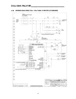
WIRING DIAGRAM, FULL VOLTAGE STARTER (STANDARD) ..................... 17


4.5b


WIRING DIAGRAM Y - DELTA START (OPTIONAL) ...................................... 18


4.6


DIRECTION OF ROTATION ............................................................................ 19


4.7


COMPRESSED AIR PIPING ............................................................................ 19


4.8


ADDITIONAL HELP .......................................................................................... 19


SECTION 5 - OPERATION ................................................................................ 20


5.1


INTRODUCTION .............................................................................................. 20


5.2


INITIAL START ................................................................................................. 20


5.3


MICRO PROCESSOR PROGRAMMING; GENERAL INSTRUCTIONS .......... 20


5.4


NORMAL OPERATION .................................................................................... 21


5.5


SHUTDOWN ..................................................................................................... 21


5.6


STARTS ............................................................................................................ 21


Summary of Contents for 125G

Page 1: ...AL FOR INDUSTRIAL ELECTRIC AIR COMPRESSORS 125 150 200 AND 250 HP UD MODELS WITH T1 MICRO PROCESSOR CONTROL PALATEK INC dba SULLIVAN PALATEK MICHIGAN CITY IN 46360 ALL RIGHTS RESERVED COPYRIGHT 2011 04 01 2011 P N OPM125 250T1 ...

Page 2: ...ON 10 3 2 COMPRESSOR UNIT 10 3 3 MOTOR 10 3 4 INTAKE CONTROL SYSTEM 10 3 5 COMPRESSOR LUBRICATION COOLING SYSTEM 13 3 6 COMPRESSOR DISCHARGE SYSTEM 13 3 7 STARTER AND ELECTRICAL PARTS 15 3 8 INSTRUMENTATION 15 SECTION 4 INSTALLATION 16 4 1 RECEIVING 16 4 1a WELDING 16 4 2 LOCATION 16 4 3 SUPPORT 16 4 4 ELECTRICAL 16 4 5a WIRING DIAGRAM FULL VOLTAGE STARTER STANDARD 17 4 5b WIRING DIAGRAM Y DELTA S...

Page 3: ...ACITY CONTROL SYSTEM 40 7 7a DISCHARGE SYSTEM 125 150 HP 42 7 7b DISCHARGE SYSTEM 200 250 HP 44 7 8a OPEN COMPRESSOR ELECTRICAL CONTROL PARTS 46 7 8b ENCLOSED COMPRESSOR CONTROL PARTS 48 7 10a AIR COOLED ENCLOSURE 125 150 50 7 10b AIR COOLED ENCLOSURE 200 250 52 7 11 WATER COOLED ENCLOSURE 54 7 12a DECAL AND IDENTIFICATION 55 7 12b DECAL AND IDENTIFICATION 56 SECTION 8 GENERAL ARRANGEMENT DRAWINGS...

Page 4: ... such as OSHA NEC NFPA CSA etc WARNING Do not modify this compressor without specific written approval from the factory 1 2 PRESSURE RELEASE Operate manually the pressure relief valve s periodically to be sure there is no blockage obstruction or inability to operate Shut machine off by use of stop button on micro processor Open and lock out disconnect switch and vent all pressure before opening or...

Page 5: ...low oil to accumulate on in or around acoustic noise material Immediately replace any oil soaked material after cleaning enclosure surface with nonflammable solvent Do not operate compressor when there is a possibility of its ingesting flammable toxic or explosive fumes mists or particles Do not operate compressor with the temperature sensor inoperative or any of its two Pressure Switches inoperat...

Page 6: ...icable regulations Use food grade lubricant for such applications 1 7 ELECTRIC SHOCK Remove watches rings and keep all parts of the body tools or other conductive objects away from exposed live parts of the electrical system Maintain dry footing stand on insulating surface and do not contact any other portion of the compressor when making adjustments Turn compressor off open main disconnect and lo...

Page 7: ...ady for maintenance service or trouble shooting if it is not running It may be in the Automatic Start mode Sleep mode or was not shut down properly prior to power having been shut off and then when power is re applied the compressor may suddenly re start thereby creating a hazardous condition Also compressor may be wired to BLT or sequencer which might call for a start Close discharge air valves a...

Page 8: ...ted over or located in such a position as to be unreadable in a given installation new Warning Signs must be ordered Be sure they are properly positioned and installed correctly WARNING If any operators are not fully conversant with the English language and or cannot comprehend the intended pictorial warnings it becomes incumbent upon the owner lesser or other responsible administrator to be sure ...

Page 9: ...or lubricant recommendations Also for such conditions we would suggest oil analysis every 1000 hours Mixing of these or any other type of oil or synthetic fluid will void the 5 year compressor unit warranty and could result in greatly increased maintenance and service expenses 2 3 APPLICATION GUIDE Ambient Temperature Range 35 to 104 F 1 to 40 C The lower temperature limit is to prevent freeze up ...

Page 10: ...r fitted with a C face register at the compressor drive end to assure proper coupling alignment at all times The main compressor motor is connectable for 230 or 460 volts The 125 250 horsepower machines utilize a separate TEFC fan motor Contact the sales representative for any other requirements such as TEFC or premium efficiency main drive motor It is recommended that these compressors be equippe...

Page 11: ...le limits in response to varying demands from the plant air service line The control regulator has an orifice that vents a small amount of control air whenever it is sending a pressure signal to the intake controller capacity control This orifice is vital to the smoothness of the control operation Unloaded and or Shutdown Modes When little or no air is being used the service line pressure will ris...

Page 12: ...______________________________SULLIVAN PALATEK 12 CONTROL SCHEMATIC ...

Page 13: ... partial flows being shared by both the oil cooler and thermovalve When fully warmed up the thermostat closes to maintain proper operating temperature The fluid filter is of the spin on replacement element type The element should be changed in accordance with the Maintenance Schedule 3 6 COMPRESSOR DISCHARGE SYSTEM The compressor unit discharges a mixture of compressed air and lubricoolant directl...

Page 14: ...shutdown or during periods of unloaded operation A pressure relief valve located upstream or on the wet side of the separator is set to open if a control malfunction would allow the pressure to exceed 200 psig 1380 kPa However since the opening of this valve is noisy and results in hot oil being expelled the micro processor control has been set to shut the motor off 10 psi above the control The pa...

Page 15: ...s is to minimize the potential for arcing at the contact points of switches or relays The primary high voltage incoming power and the secondary control voltage circuits are both provided with breakers to minimize the potential for damage due to overloading or short circuit faults In addition a 24 volt output transformer is needed to supply the proper operating voltage for the micro processor contr...

Page 16: ...ry for assistance if heat recovery is desired Model 125G 150G 200G 250G AIRFLOW CFM 12 500 15 000 18 500 20 000 HEAT REJECTION BTU HR 330 000 418 500 550 000 600 000 Locate compressor as close as practical to where the compressed air is to be utilized This saves piping and reduces power requirements necessary to transmit compressed air long distances The compressor should be piped into a receiver ...

Page 17: ...SULLIVAN PALATEK______________________________ 17 4 5a WIRING DIAGRAM FULL VOLTAGE STARTER STANDARD ...

Page 18: ...______________________________SULLIVAN PALATEK 18 4 5b WIRING DIAGRAM Y DELTA START OPTIONAL ...

Page 19: ...pipe Point of use filters coalescers regulators and or lubricators are often required Note Never use plastic air piping or plastic bowls on filters or lubricators See Section 1 Inspect piping and air hoses frequently for leaks 4 8 ADDITIONAL HELP By making the cleanest coolest air available to the compressor inlet maintenance and power consumption will be minimized The standard air filter is local...

Page 20: ...ervice air valve closed allow machine to pump up to normal operating pressures and observe operation of automatic controls and look for any possible leaks Open service air valve and check operation throughout the range of pressures observing operating temperatures Push red stop button and check lubricoolant level after it has been allowed to settle for a few minutes If it is necessary to add lubri...

Page 21: ... service valve allow sump pressure to fall to 40 45 PSI then press stop button on micro processor control 5 6 STARTS After a power failure open and lock out the main disconnect check all fuses and breakers Close disconnect switch and follow Normal Operation start up procedure Following a shutdown caused by either of the protective devices i e temperature or R O P open and lock out the main disconn...

Page 22: ...t analysis Replace air and oil filter elements and air oil separator element sooner if excessive lubricoolant loss is experienced FOOD GRADE LONG LIFE Every 4 000 hours If using Food Grade Long Life Change Food Grade Long Life lubricoolant and inspect tank interior Replace lubricant filters and air oil separator element PALLUBE 32p LUBRICANT Every 8 000 hours If using Pallube 32p Change Pallube 32...

Page 23: ... once the filter element has been replaced 6 4 AIR OIL SEPARATOR Replace annually or if differential pressure exceeds 8psid i e fault signal is shown on micro processor H5 1 Open and lock out main disconnect 2 Disconnect main air line to aftercooler 3 Disconnect control air tubing 4 Unbolt cover in a diagonal criss cross pattern 5 Remove cover oil pick up tube and separator element 6 Drain lubrico...

Page 24: ...o store this setting I Press down key to get to the load pressure Pl this is normally set at a pressure 8 to 12 PSI below the unload pressure J Press enter then use up or down keys to change setting K Press enter to store setting L Press reset double bar for 2 seconds to return to normal display M Press down arrow to get the temperature display 6 6 SERVICE MAINTENANCE PROCEDURES All service parame...

Page 25: ...5 Low incoming line voltage Check voltage Should voltage check low consult your power company 6 Power failure see start up 7 Unit locked up a Filled with oil leaking inlet valve Replace inlet valve b Unit failure replace unit SYMPTOM PROBABLE CAUSES AND REMEDIES B MACHINE SHUTS DOWN WITH AIR DEMAND PRESENT 1 Loss of control voltage Reset If trouble persists check that line pressure does not exceed...

Page 26: ...l Add lubricoolant d Clogged oil filter Change the oil filter element e Thermostat not working properly Replace f Check for proper cooling fan operation Fan should always be running between 165 to 190 F SYMPTOM PROBABLE CAUSES AND REMEDIES C MACHINE WILL NOT BUILD UP FULL DISCHARGE PRESSURE 1 Air demand too great Repair system air leaks Add compressor capacity to satisfy demand 2 Dirty air filter ...

Page 27: ...ABLE CAUSES AND REMEDIES E EXCESSIVE LUBRICOOLANT CONSUMPTION 1 Clogged oil return line Clean strainer and or orifice 2 Separator element is damaged or not functioning properly Change separator 3 Leak in lubrication system Check all pipes connections and components 4 Defective inlet valve Repair inlet valve 5 Operating pressure below 60 psig Repair minimum pressure valve SYMPTOM PROBABLE CAUSES AN...

Page 28: ...______________________________SULLIVAN PALATEK 28 PARTS LISTING ...

Page 29: ...n an exchange basis All bearings and seals have been replaced All other parts not meeting our quality standards are also replaced The air end is then factory tested prior to shipment A re manufactured air end has a warranty which is 12 months from start up date or 18 months from date of shipment in accordance with the terms set forth in the new air end warranty found on pages 62 63 ...

Page 30: ...00521 112 1 2 ELEMENT OIL FILTERS 00520 016 00520 016 2 3 ELEMENT SEPARATOR 125 250 HP K08000 024 K08000 024 1 4 KIT REGUL VALVE REPAIR K09661 002 K09661 002 1 5 VALVE PRESSURE RELIEF 03100 006 03100 006 1 6 SENSOR TEMP 69677 001 69677 001 1 7 PRESSURE TRANSDUCER 69676 006 69676 006 1 8a PALASYN 45 LUBRICOOLANT 5 GAL 00061 005 00061 005 5 8b PAL EXTRA 44 LUBRICOOLANT 5 GAL OPT SEVERE DUTY 00066 00...

Page 31: ...SULLIVAN PALATEK______________________________ 31 DRIVE AND BASE ASSEMBLY ...

Page 32: ...______________________________SULLIVAN PALATEK 32 7 3 DRIVE AND BASE ASSEMBLY PARTS LIST ...

Page 33: ...SULLIVAN PALATEK______________________________ 33 LUBRICATION AND COOLING SYSTEM AIR COOLED ...

Page 34: ...______________________________SULLIVAN PALATEK 34 7 4 LUBRICATION AND COOLING SYSTEM AIR COOLED ...

Page 35: ...SULLIVAN PALATEK______________________________ 35 LUBRICATION AND COOLING SYSTEM WATER COOLED 125 150 ...

Page 36: ...______________________________SULLIVAN PALATEK 36 7 5a LUBRICATION AND COOLING SYSTEM WATER COOLED 125 150 ...

Page 37: ...SULLIVAN PALATEK______________________________ 37 LUBRICATION COOLING SYSTEM W C 200 250 ...

Page 38: ...______________________________SULLIVAN PALATEK 38 7 5b LUBRICATION COOLING SYSTEM W C 200 250 ...

Page 39: ...SULLIVAN PALATEK______________________________ 39 INLET AND CAPACITY CONTROL SYSTEM ...

Page 40: ...______________________________SULLIVAN PALATEK 40 7 6 INLET AND CAPACITY CONTROL SYSTEM Item 14 Recommend Rebuilding Inlet Valve with K09790 005 Kit every 2 Years ...

Page 41: ...SULLIVAN PALATEK______________________________ 41 DISCHARGE SYSTEM 125 150 HP ...

Page 42: ...NIT TO DISCHARGE PIPE 1 20 00910659 0237 O RING SEAL TO ADAPTER 1 21 92581 200 WASHER LOCK 20MM 4 22 95201 449 BOLT HHC 20MM X 60MM 4 23 90305 064 WASHER LOCK 625 20 24 90169 006 NUT HEX 5 8 GR8 4 25 19600 065 PIPE DISCHARGE 3 000 1 26 93165 006 NUT WHIZ HEX 1 2 13 4 27 00909753 0048 FLANGE ASSEMBLY 3 000 CODE 61 1 28 90042 432 BOLT HH 5 8 X 1 625 GR8 4 29 92141 005 FITTING BULKHEAD 625 TUBE X 500...

Page 43: ...SULLIVAN PALATEK______________________________ 43 DISCHARGE SYSTEM 200 250 HP ...

Page 44: ...0042 095 BOLT GR8 5 8 X 3 000 4 17 90708 008 GASKET 150 RF 3 000 FLANGE 1 18 00633 018 GASKET E75 AIR END TO DISCHARGE 1 19 92581 200 WASHER LOCK 20MM 4 20 90305 064 WASHER LOCK 625 16 21 90169 006 NUT HEX 5 8 GR8 4 22 95201 426 BOLT HHC 20MM X 60MM 4 23 19600 041 PIPE DISCHARGE 3 000 1 24 90165 005 NUT HEX 1 2 13 4 25 90305 004 WASHER LOCK 500 4 26 90321 005 WASHER USS FLAT 500 8 27 96391 108 ELB...

Page 45: ...SULLIVAN PALATEK______________________________ 45 OPEN COMPRESSOR ELECTRICAL CONTROL PARTS ...

Page 46: ...______________________________SULLIVAN PALATEK 46 7 8a OPEN COMPRESSOR ELECTRICAL CONTROL PARTS ...

Page 47: ...SULLIVAN PALATEK______________________________ 47 ENCLOSED COMPRESSOR CONTROL PARTS ...

Page 48: ...______________________________SULLIVAN PALATEK 48 7 8b ENCLOSED COMPRESSOR CONTROL PARTS ...

Page 49: ...SULLIVAN PALATEK______________________________ 49 AIR COOLED ENCLOSURE 125 250 ...

Page 50: ...______________________________SULLIVAN PALATEK 50 7 10a AIR COOLED ENCLOSURE 125 150 ...

Page 51: ...SULLIVAN PALATEK______________________________ 51 AIR COOLED ENCLOSURE 200 250 ...

Page 52: ...______________________________SULLIVAN PALATEK 52 7 10b AIR COOLED ENCLOSURE 200 250 ...

Page 53: ...SULLIVAN PALATEK______________________________ 53 WATER COOLED ENCLOSURE ...

Page 54: ...______________________________SULLIVAN PALATEK 54 7 11 WATER COOLED ENCLOSURE ...

Page 55: ...832 043 03832 043 2 DECAL VOLTAGE 460 1 08377 001 08377 001 08377 001 3 DECAL WARNING 1 08377 043 08377 043 08377 043 4 DECAL WARNING 1 08377 045 08377 045 08377 045 5 DECAL WARNING 1 08377 046 08377 046 08377 046 6 DECAL 3 POS SWITCH 1 08378 048 08378 048 08378 048 7 DECAL INSTRUCTIONS 1 08379 011 08379 011 08379 011 8 DIAGRAM WIRING 1 12288 003 12288 005 12288 005 ...

Page 56: ...______________________________SULLIVAN PALATEK 56 7 12b DECAL AND IDENTIFICATION ...

Page 57: ...SULLIVAN PALATEK______________________________ 57 SECTION 8 GENERAL ARRANGEMENT DRAWINGS 8 1 PIPING INSTALLATION DIAGRAM 125 250 HP ...

Page 58: ...______________________________SULLIVAN PALATEK 58 8 2 GENERAL ARRANGEMENT OPEN AIR COOLED 125 250 ...

Page 59: ...SULLIVAN PALATEK______________________________ 59 8 3 GENERAL ARRANGEMENT OPEN WATER COOLED 125 250 ...

Page 60: ...______________________________SULLIVAN PALATEK 60 8 4 GENERAL ARRANGEMENT ENCLOSED AIR COOLED 125 150 ...

Page 61: ...SULLIVAN PALATEK______________________________ 61 8 5 GENERAL ARRANGEMENT ENCLOSED AIR COOLED 200 250 ...

Page 62: ...______________________________SULLIVAN PALATEK 62 8 6 GENERAL ARRANGEMENT ENCLOSED WATER COOLED 125 250 ...

Page 63: ...ervice performed by someone other than a party authorized to perform warranty service if such service in the judgment of Sullivan Palatek has adversely affected the performance of the compressor the consequences of negligence misuse accident installation or storage The consequences of compressor lubrication neglect as manifested by varnishing pitting erosion of the rotors or stator or both Any pre...

Page 64: ...nd startup card supplied with the compressor must be completed and returned within 10 days of delivery and start up to register the compressor in to the Platinum program Eligibility for the Platinum warranty will expire 180 days after shipment of the product from the factory and can only be reestablished by application to the Sullivan Palatek Product Support department which may require a paid on ...

Page 65: ...ENANCE LOG S N SERVICE DIST FILL OUT FOR EACH SERVICE OR REPAIR MORE THAN ONE LINE MAY BE USED PER EACH SERVICE OR REPAIR THIS FORM MAY BE PHOTOCOPIED AS NEEDED DATE HOURS TEMP LINE PRESS OIL RET CLEAR OIL LEVEL SERVICE CHANGE CHANGED PART NUMBER SERVICE BY AIR OIL FILTER SEP ELE OIL ...

Page 66: ...ENANCE LOG S N SERVICE DIST FILL OUT FOR EACH SERVICE OR REPAIR MORE THAN ONE LINE MAY BE USED PER EACH SERVICE OR REPAIR THIS FORM MAY BE PHOTOCOPIED AS NEEDED DATE HOURS TEMP LINE PRESS OIL RET CLEAR OIL LEVEL SERVICE CHANGE CHANGED PART NUMBER SERVICE BY AIR OIL FILTER SEP ELE OIL ...

Reviews: