NOTES
24
A pressure relief valve (located on the wet side of the
separator) is set to open if the sump pressure
exceeds the rated pressure of the tank. For added
safety the Supervisor is programmed to shutdown
the package when:
a.
A pressure level, above unload setting but
below relief valve setting, is reached.
b.
A temperature level exceeding 235ºF
(113ºC) is reached.
See Supervisor functional description for further
details on shutdown pressure levels.
The high pressure shutdown protection will shut
down the compressor at 20 psig (1.4 bar) above
rated pressure. This prevents the pressure relief
valve from opening under routine conditions, thereby
preventing fluid loss through the pressure relief
valve. Temperature is monitored via the controller
and will shut down the compressor if the discharge
temperature reaches 235ºF (113ºC).
Fluid is added to the sump via a capped fluid filler
opening, placed low on the tank to prevent overfilling
of the sump. Two sight glasses enable the operator
to visually monitor the sump fluid level.
2.5
CONTROL SYSTEM,
FUNCTIONAL DESCRIPTION
and
purpose of the compressor control system is to
regulate the amount of air being compressed to
match the amount of compressed air being used.
The capacity control system consists of a spiral valve
and an inlet butterfly valve. The functional description
of the control system is described below in 4 distinct
phases of compressor operation. The following
applies to TS32 Series compressors ranging from
400 through 600hp (298-447kw). For explanatory
purposes, this description applies to any compressor
with an operating range of 100 to 110 psig (6.9 to 7.6
bar). A compressor with any other pressure range
would operate in the same manner except for the
stated pressures.
START MODE—0 TO 50 PSIG (0 TO 3.4
BAR)
When the compressor (ON)
pad is
depressed, the sump pressure will quickly rise from 0
to 50 psig (0 to 3.4 bar). During this period, both of
the pressure regulators and the solenoid valve are
closed and the Sullicon Control and spiral valve are
inoperative. The spring on the control holds the
butterfly valve fully open while the spiral valve is fully
closed (maximum) position and the compressor
pumps at full rated capacity. The rising compressor
air pressure is isolated from the service line in this
phase by the minimum pressure valve set at
approximately 50 psig (3.4 bar). An optional closed
inlet system is provided which uses air pressure to
close the butterfly and opens the spiral valve to
reduce motor torque for starting.
FULL LOAD MODE—50 TO 100 PSIG (3.4
TO 6.9 BAR)
50 TO 100 PSIG (3.4 TO 6.9 BAR) When the
compressed air pressure in the sump rises above 50
psig (3.4 bar), the minimum pressure valve opens,
allowing compressed air to flow into the service line.
From this point on, the line air pressure is continually
monitored by the Supervisor. The pressure
regulators and the solenoid valve remain closed
during this phase, keeping the Sullicon Control and
spiral valve inactive. Both the spiral valve as well as
the inlet butterfly valve remain in the full load position
as long as the compressor is running at 100 psig (6.9
bar) or below.
MODULATING MODE—100
TO
110 PSIG
(6.9 TO 7.6 BAR)
100 TO 110 PSIG (6.9 TO 7.6 BAR) As air demand
drops below the rated capacity of the compressor,
the line pressure will rise above 100 psig (6.9 bar).
As a result, the differential pressure regulator for the
spiral valve gradually opens, applying air pressure to
the spiral valve actuator. Air pressure at the actuator
WARNING
DO NOT remove caps, plugs, and/or other
components when compressor is running
or pressurized.
Stop compressor and relieve all internal
pressure before doing so.
NOTE
Always refer to the machine nameplate for
designed operating pressure.
Summary of Contents for TS32 AC
Page 10: ...NOTES 10...
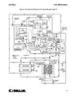
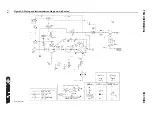
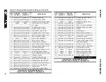
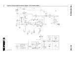
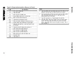
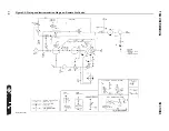
Page 15: ...SECTION 2 TS32 USER MANUAL 15 Figure 2 3 Compressor Piping and Instrument Diagram Typical...
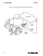
Page 16: ...TS32 USER MANUAL SECTION 2 16 Figure 2 4 Compressor Cooling and Lubrication System Air cooled...
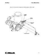
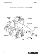
Page 18: ...TS32 USER MANUAL SECTION 2 18 Figure 2 6 Compressor Discharge System Air cooled 200 350HP...
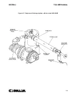
Page 19: ...SECTION 2 TS32 USER MANUAL 19 Figure 2 7 Compressor Discharge System Water cooled 200 350HP...
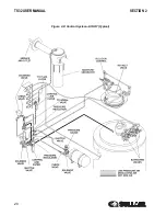
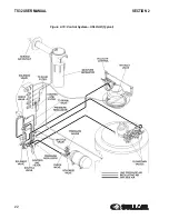
Page 20: ...TS32 USER MANUAL SECTION 2 20 Figure 2 8 Control System START Typical...
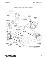
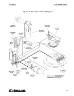
Page 21: ...SECTION 2 TS32 USER MANUAL 21 Figure 2 9 Control System MODULATION Typical...
Page 22: ...TS32 USER MANUAL SECTION 2 22 Figure 2 10 Control System UNLOAD Typical...
Page 23: ...SECTION 2 TS32 USER MANUAL 23 Figure 2 11 Control System FULL LOAD Typical...
Page 26: ...TS32 USER MANUAL SECTION 2 26 Figure 2 12 Compressor Air Inlet System...
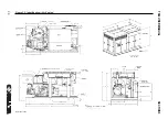
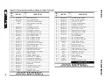
Page 30: ...TS32 USER MANUAL SECTION 3 30 Figure 3 2 Identification Air Cooled 02250126 376 R02...
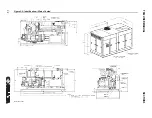
Page 32: ...TS32 USER MANUAL SECTION 3 32 Figure 3 2 Identification Water Cooled 02250126 378 R03...
Page 50: ...TS32 USER MANUAL SECTION 3 50 Figure 3 9 Wiring Diagram Air Cooled SSRV 02250178 844 R03...
Page 54: ...NOTES 54...
Page 78: ...NOTES 78...
Page 79: ...NOTES 79...

