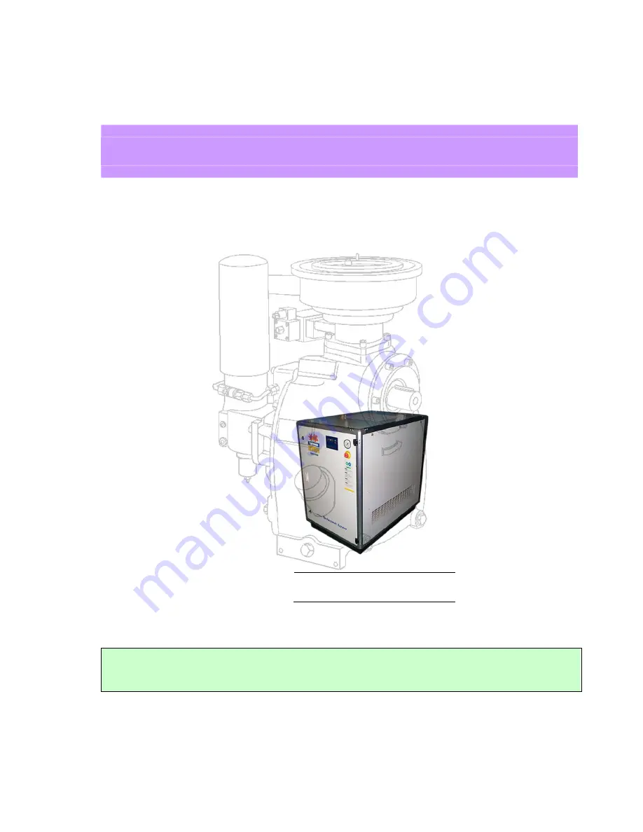
background image

COAIRE M-Series 

EXTROLLER Control System 


MAINTENANCE MANUAL AND  PARTS LIST 


MODEL 


CHSA-7.5M      CHSA-10M 

CHSA-15M        CHSA-20M 


SERIAL NO. : 


MODEL NO. : 


MODEL     CHSA-15CHSA-20M 

COAIRE TECHNOLOGIES, CORPORATION 


All rights reserved                                                                                                                  Printed in  USA

ROTARY SCREW AIR COMPRESSORS


For proper and safe use of the compressor, please follow all instructions and safety precautions as identified in 

this manual, along with general safety regulations and practices. 


Summary of Contents for CHSA-10M

Page 1: ...0M SERIAL NO MODEL NO MODEL CHSA 15CHSA 20M COAIRE TECHNOLOGIES CORPORATION All rights reserved Printed in USA ROTARY SCREW AIR COMPRESSORS For proper and safe use of the compressor please follow all instructions and safety precautions as identified in this manual along with general safety regulations and practices ...

Page 2: ...ognized electrical procedure Before working on the electrical system ensure that the system s power has been shut off by use of a manual disconnect switch A circuit breaker or fuse switch must be provided in the electrical supply line to be connected to the compressor The preparation work for installation of this unit must be done in suitable grounds maintenance clearance and lighting arrestors fo...

Page 3: ...rization Said authorization may be obtained through our air compressor service department All air compressors parts materials must be returned freight prepaid to the Manufacturer s factory within 30 days of return authorization date Any shipment returned to the factory collect will be refused If an item is found to be warrantable the repaired item or replacement will be returned normal ground frei...

Page 4: ... 3 6 After cooler oil cooler 14 3 7 Oil separator 14 3 8 Oil Filter 14 3 9 Thermostatic Valve 14 3 10 Min Pressure Valve 14 3 11 Air Intake Filter 14 3 12 Instrument Panel 15 3 13 Starter and control box 15 3 14 Safety device 15 Chapter Ⅳ Scheduled Maintenance 4 1 Standard maintenance schedule 16 4 2 Control of lubrication 17 Chapter Ⅴ Trouble shooting 5 1 Trouble symptoms and solutions 19 5 2 Ope...

Page 5: ...on Process 1 2 2 COMPRESSION PROCESS The air in the void is compressed as the male rotor lobe meshes between the female rotor lobes and squeezes the air against discharge cover Fig 1 2 Compression Process 1 2 3 OIL INJECTION PROCESS As pressure builds oil is injected into the compression area and onto the bearings and shaft seal serving to lubricate absorb compression heat and seal the rotors Fig ...

Page 6: ...pact at the inner wall of the oil separator and by the fluid cyclonic effect After primary separation the heavy oil falls and is collected in the oil sump at the bottom of the oil separator Secondary separation The air which still contains fine oil particles flows through the oil separator element where the oil forms into large particles and is collected at the bottom of the element shell Then cle...

Page 7: ...erature 32 115 Discharge air temperature Inlet air temperature 27 MAX Driving method V Belt V Belt Voltage V 3Ph 1Ph 208 230V 3Ph 208 230 460V Frequency Hz 60 Starting method Direct on Start Oil sump capacity gal 0 7 0 7 1 1 Noise level dB A 68 70 71 Weight lbs 300 310 420 Dimensions W D H in 17 24 5 8x32 5 8 28 3 4x41 3 8x42 1 8 Air outlet piping size in 3 4 1 Air Cleaner Solenoid Valve Only 15 3...

Page 8: ... 4x41 3 8x42 1 8 31 1 2x47 1 4x49 7 8 Air outlet piping size in 1 1 1 9 INSTALLATION AND WIRING Upon delivery carefully check the air compressor unit s for damage during transportation 1 9 1 HANDLING When handling by a forklift make sure that forks completely extend through the width of the unit When handling by a shop crane use the openings provided on common base where slings or steel wire ropes...

Page 9: ...higher than 115 may cause compressor shutdown or severe damage to the unit HEAT GENERATION VENTILATION FAN CAPACITY MODEL CAPACITY CHSA 7 5M CHSA 10M CHSA 15M CHSA 20M CHSA 25M CHSA 30M CAPACITY Btu h AIR VOLUME cfm 1165 1235 1900 2120 2330 2540 Note 1 The room ventilation capacity is based on 1 Compressor room Temperature rise which is controlled within the 9 2 Static pressure of ventilation air ...

Page 10: ...ection of compressor unit to the end of the piping the use of air receiver is recommended In case the discharge piping has to be unusually long you should select the diameter of the piping in considering the pressure drop in the piping Consult your distributor for proper technical support Fig 1 9 Parallel installation Fig 1 10 Installation with reciprocating compressor 1 9 4 ELECTRICITY This exten...

Page 11: ... FRAME AF TRIP A TRIP A POWER KIV GROUND GV DIRECT Y DELTA CHSA 7 5M 5 59 7 5 6 39 208 19 0 70 8 94 30 30 22 8 3 5 1 25 230 17 0 64 0 30 30 20 4 3 5 1 25 460 8 5 32 0 30 15 10 2 2 1 25 CHSA 10M 7 46 10 8 43 208 25 6 74 1 91 50 40 30 72 5 5 2 230 23 2 67 0 50 40 27 84 5 5 2 460 11 6 38 5 30 20 13 92 3 5 1 25 CHSA 15M 11 19 15 13 3 208 38 7 137 1 90 60 60 46 44 8 3 5 230 35 0 124 0 60 60 42 8 3 5 46...

Page 12: ...rd Reinstall guard prior to any further running 2 1 2 STARTING Turn on the main disconnection switch Power lamp on air compressor instrument panel lights up Press start key on operating panel of the unit The running lamp on the unit operating panel lights up Check the rotation While checking proper rotation you should not run the machine for 5 sec or more If you do not the air end will be damaged ...

Page 13: ...TION Drain the condensation from after cooler Check oil level Proper oil level is at centerline of upper oil level gage with machine not running STARTING Press START key DURING THE OPERATION Check oil level gauge Make sure that all gauges in compressor instrument panel indicates normal status and followings SPECIFICATION UNIT Limit Remarks Discharge temperature Less Than 203 Ambient Temperature Le...

Page 14: ...et point Adjustable Range 1 Compressor discharge shut down temperature 220 176 230 2 Start idling time 5 Sec 5 10 Sec 3 Unloading control time 5 Min 5 10 Min 4 Stop control time 30 Sec 20 50 Sec 5 Drain valve off time 5 Min 1 45 Min 6 Drain valve on time 1 sec 1 5 Sec 7 Discharge pressure 110 Psi 80 190 PSI ...

Page 15: ...ated to support radial loads With a differential pressure lubrication system the compres sor can dispense with an oil pump thus dramatically simplifying the oil supply system The wedge construction of the secondary sealing element of the mechanical seal naturally eliminates leakage This seal is highly reliable and excellent performance 3 1 1 ROTORS The male rotor has five lobes and the female roto...

Page 16: ...m discharged air 3 8 OIL FILTER Oil filter element is located at the air end which efficiently filtering foreign material from circulating oil The oil filter has from 5 to 10 micron paper cartridge and it should be replaced every 1000 run hours normally 3 9 THERMOSTATIC VALVE This is the oil by pass valve Located in the oil cooler outlet pipe in order to maintain adequate system temperature for ef...

Page 17: ...VICE Shutdown switch for discharge high air temperatures Differential shutdown switch for oil filter Differential shutdown switch for oil separator element Overload for motor Overload for cooling fan motor Safety valve ...

Page 18: ...tenance Interval Remark Daily Monthly 6 Monthly Annually 2 yearly 4 yearly 1000 Hrs 3000 Hrs 6K HRS 12K HRS 24K Hrs Oil Separator Oil Level Check Condensation Drain Oil Sampling Replace Oil Tank Clean Level Gauge Clean O ring Gasket Replace Monitor Check Air Filter Element Replace Separator Cartridge Replace Oil Filter Cartridge Replace After Cooler Clean Intake Suction Valve Clean Repair Safety V...

Page 19: ...or if a certain brand of oil must be replaced with another be sure to flush out the oil system first Consult your distributor for the procedures We highly recommended the use of Genuine COAIRE Screw Compressor Oil COAIRE COLUBE 68 4 2 2 OIL CHANGE A practical way is to change the oil at the following intervals First oil change 500 hours after initial start up Second oil change 1 500 hours after th...

Page 20: ...ty 30 minutes may be enough for sufficient separation of oil from condensation WARNING Even if the unit is in 24 hour continuous service it is still recommended to perform a draining procedure Normally in such an operation mode an extra stand by compressor has to be installed at the same time to allow for better draining of condensation CAUTION LUBRICANT Avoid prolonged breathing of vapors Always ...

Page 21: ... source voltage 4 High discharge temperature safety shutdowns a high ambient temperature a Improve room ventilation b Low oil Level b Add oil as necessary c Oil cooler c 1 Clogged inside tube c 1 Clean or replace c 2 Dirt accumulation on fins c 2 Clean d Oil filter clogged d Clean or replace element e Failure of oil temperature regulating valve e Check or replace f Insufficient cooling air flow f ...

Page 22: ...N 8 f c High ambient temperature c See CONDITION 4 a d Water included in oil d See CONDITION 8 f e Scheduled oil change neglected e See CONDITION 8 f 10 Noise and vibration a Loose components and joints a Retighten b From air end b Consult the distributor b 1 Bearing demand or worn b 2 Foreign material c V belt slip c Adjust tension or replace d Wrong installation of the unit d Correct the install...

Page 23: ...9 5 2 OPERATION RECORD FORM Replaced parts and other particulars Total running hours Quantity of refill oil gal Ambient Temperature F Discharge pressure Psig Oil Temperature F Motor Voltage V Amp A Date ...

Page 24: ...nit has run for a while and warmed up properly To replace the oil filter element please take the following steps Stop the unit and make sure that the discharge pressure gauge indicates 0 psig Rotate the oil filter in a clockwise rotation when viewed from the bottom of the filter Remove the filter element and make certain the seal is also removed Clean the inner su rface of filter head Grease the g...

Page 25: ... Filter CAUTION The second stage polyester element may be washable five times at a maximum Do not fail to discard the used element and replace it with a new one 6 3 OIL SEPARATOR CARTRIDGE Oil separator cartridge is located at the upper part of air end Oil separator cartridge separates the fine oil mist from the air Separated oil is collected at the bottom of the cartridge and is scavenged to the ...

Page 26: ...d tested Maximum oil leakage 3 cc h Consult your distributor CAUTION Do not install anything to block the drain tube such as a stop valve The drain tube should be open to the atmosphere in order to check for the mount oil leak in the event of such incident 6 5 MINIMUM PRESSURE VALVE Minimum pressure valve is located on the compressor discharge line after the separator tank The valve is set at 57 p...

Page 27: ...dust by covering it Disassemble the suction control valve Remove the gasket or o ring from groove Use care so the gasket surface or the groove is not damaged Inspect the Butterfly valve and non return valve for any damage or scratches Mount the suction control valve on the air end Tighten the bolts and set screws Reconnect all the piping Make sure that the installati on positions are correct Open ...

Page 28: ...ions are approximately the same value as in the table below Fig 6 14 V Belt tension 6 9 2 TENSION READJUSTMENT AND ALIGNMENT If necessary readjust the tension as follow Isolate main power Loosen the lock bolts located at the motor base Loosen the tightening nuts of adjusting bolts Tighten the adjusting bolts until the correct tension is obtained If necessary inspect the alignment as follows Motor ...

Page 29: ...ngs of the pressure switch every 500 hours of operation or monthly basis whichever comes first If cut out pressure settings are not proper readjust as follows Differential Cut out pressure cut in pressure Therefore the value of standard factory setting is 25 6 psig NOTE Generally the narrower differential needs a larger air receiver and vice versa However please be advised that using an unnecessar...

Page 30: ...HSA 7 5 10M 3 4 Oil Filter 1 5 CHSA 7 5 10M 3 5 Temperature Prove Connection 1 6 CHSA 7 5 10M 3 6 Oil Circuit Out 1 7 CHSA 7 5 10M 3 7 Oil Reservoir 1 8 CHSA 7 5 10M 3 8 Oil Circuit In 1 9 CHSA 7 5 10M 3 9 Safety Valve 1 10 CHSA 7 5 10M 3 10 Air Intake 1 11 CHSA 7 5 10M 3 11 Compressed Air Outlet 1 12 CHSA 7 5 10M 3 12 Port For Pressure Transmitter 1 13 CHSA 7 5 10M 3 13 Oil Filler Plug 1 14 CHSA ...

Page 31: ...27 AIR END NK40 ...

Page 32: ... 4 Oil Filter 1 5 CHSA 15 20M 3 5 Temperature Prove Connection 1 6 CHSA 15 20M 3 6 Oil Circuit Out 1 7 CHSA 15 20M 3 7 Oil Reservoir 1 8 CHSA 15 20M 3 8 Oil Circuit In 1 9 CHSA 15 20M 3 9 Safety Valve 1 10 CHSA 15 20M 3 10 Air Intake 1 11 CHSA 15 20M 3 11 Compressed Air Outlet 1 12 CHSA 15 20M 3 12 Port For Pressure Transmitter 1 13 CHSA 15 20M 3 13 Minimum Pressure Valve 1 14 CHSA 15 20M 3 14 Oil...

Page 33: ...29 AIR END NK60 ...

Page 34: ...30 Appendix B 1 PART LIST FOR MODEL CHSA 7 5M 1 2 ...

Page 35: ...31 1 PART LIST FOR MODEL CHSA 7 5M 2 2 ...

Page 36: ...32 2 PART LIST FOR MODEL CHSA 10M 1 2 ...

Page 37: ...33 2 PART LIST FOR MODEL CHSA 10M 2 2 3 PART LIST FOR MODEL CHSA 15M 1 2 ...

Page 38: ...34 3 PART LIST FOR MODEL CHSA 15M 2 2 ...

Page 39: ...35 4 PART LIST FOR MODEL CHSA 20M 1 2 ...

Page 40: ...36 ...

Page 41: ...37 4 PART LIST FOR MODEL CHSA 20M 2 2 ...

Page 42: ...38 C Wiring Diagram for Model CHSA 7 5 10 15 20M ...

Page 43: ...39 Appendix D 1 Outline Drawing for Model CHSA 7 5 10M ...

Page 44: ...40 2 Outline Drawing for Model CHSA 15 20M ...

Page 45: ...ature F No of days of operation weekly Days Discharge temperature F Hours per day Hours Compressor area temperature F Machine setting OL OL or Mod Environment 1 1 1 to 10 1 being clean 10 very dirty Incoming Voltages Full load amperage at _______ PSIG Unload amperage at ______ PSIG L1 L2 L2 L3 L1 L3 L1 L2 L2 L3 L1 L3 L1 L2 L2 L3 L1 L3 Volts Amp Amp Amp Amp Amp Amp Amp Amp Symptom Fault Diagnosis R...

Page 46: ... Unload amperage at _________ PSIG L1 L2 L3 Amp Amp Amp Is the machine on a level and stable surface Yes No Did you have to add lubricant oil Yes No if yes please indicate amount and exact name and type Amount _______ Name _______ Type _______ Was a flexible connector used to connect piping Yes No Approx time spent during startup procedure ___________ Hrs Did you advice customer on operation and m...

Page 47: ...MISE TECHNOLOGIES CORP 8740 Pioneer Blvd Santa Fe Springs CA 90670 TEL 562 463 3935 ㆍ FAX 562 463 4928 COAIRE reserves the right to make changes at any time without notice as a result of our commitment to continuous improvement COAIRE CHSA M07 ...

Reviews: