SECTION 4
TS32 USER MANUAL
59
O
UTDOOR
I
NSTALLATION
(S
HELTERED
)
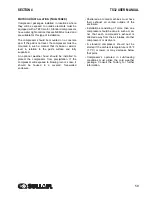
Compressor packages installed in locations where
they will be exposed to outside elements must be
equipped with a TEFC motor. Standard compressors
have water tight controls that are NEMA 4 rated and
are suitable for this type of installation.
The compressor should be mounted on a concrete
pad. If the pad is not level, the compressor must be
mounted in such a manner that its base or skid is
level in relation to the pad’s surface and fully
supported.
An optional weather hood should be installed to
protect the compressor from precipitation. If the
compressor will exposed to blowing rain or snow, it
should be housed in a covered, four-walled
enclosure.
• Sheltered air-cooled machines must have
their exhaust air vented outside of the
enclosure.
• Installations consisting of more than one
compressor should be done in such a man-
ner that each compressor’s exhaust is
directed away from the air intakes of other
compressors or air dryers.
• A standard compressor should not be
started if the ambient temperature is 35°F
(1.7°C) or lower, or may decrease below
that point.
• Compressor’s operated in sub-freezing
conditions must utilize the cold weather
package. Consult the factory for further
information.
Summary of Contents for TS32 AC
Page 10: ...NOTES 10...
Page 15: ...SECTION 2 TS32 USER MANUAL 15 Figure 2 3 Compressor Piping and Instrument Diagram Typical...
Page 16: ...TS32 USER MANUAL SECTION 2 16 Figure 2 4 Compressor Cooling and Lubrication System Air cooled...
Page 18: ...TS32 USER MANUAL SECTION 2 18 Figure 2 6 Compressor Discharge System Air cooled 200 350HP...
Page 19: ...SECTION 2 TS32 USER MANUAL 19 Figure 2 7 Compressor Discharge System Water cooled 200 350HP...
Page 20: ...TS32 USER MANUAL SECTION 2 20 Figure 2 8 Control System START Typical...
Page 21: ...SECTION 2 TS32 USER MANUAL 21 Figure 2 9 Control System MODULATION Typical...
Page 22: ...TS32 USER MANUAL SECTION 2 22 Figure 2 10 Control System UNLOAD Typical...
Page 23: ...SECTION 2 TS32 USER MANUAL 23 Figure 2 11 Control System FULL LOAD Typical...
Page 26: ...TS32 USER MANUAL SECTION 2 26 Figure 2 12 Compressor Air Inlet System...
Page 30: ...TS32 USER MANUAL SECTION 3 30 Figure 3 2 Identification Air Cooled 02250126 376 R02...
Page 32: ...TS32 USER MANUAL SECTION 3 32 Figure 3 2 Identification Water Cooled 02250126 378 R03...
Page 50: ...TS32 USER MANUAL SECTION 3 50 Figure 3 9 Wiring Diagram Air Cooled SSRV 02250178 844 R03...
Page 54: ...NOTES 54...
Page 78: ...NOTES 78...
Page 79: ...NOTES 79...

