Section 2
DESCRIPTION
11
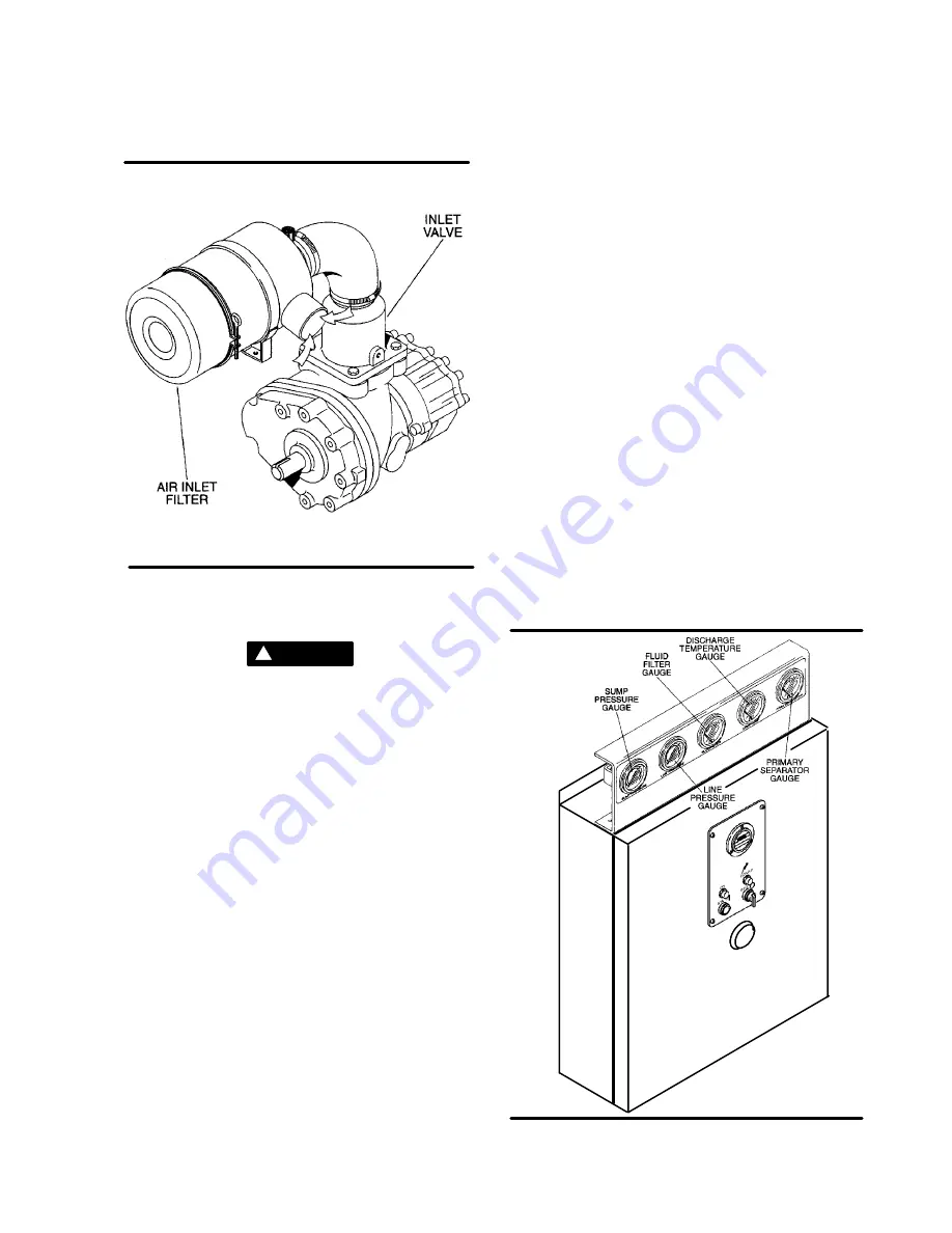
Figure 2---4 Air Inlet System
valve, thus preventing reverse rotation when the
compressor is shut down.
WARNING
!
“The Plastic Pipe Institute recommends against the
use of thermoplastic pipe to transport compressed
air or other compressed gases in exposed above
ground locations, e.g. in exposed plant piping.” (
I
)
Sullube 32 should not be used with PVC piping sys-
tems. It may affect the bond at cemented joints. Cer-
tain other plastic materials may also be affected.
(
I
) Plastic Pipe Institute, Recommendation B,
Adopted January 19, 1972.
2.9 INSTRUMENT PANEL GROUP, FUNCTIONAL
DESCRIPTION-- STANDARD ELECTRO/ME-
CHANICAL
Refer to Figure 2---5 for specific location of parts de-
scribed. The Instrument Panel group consists of a
panel containing the
line pressure
,
sump pres-
sure
and
discharge temperature gauges
, the
separator element
and the
fluid filter
,
restriction
gauges
, along with
START
and
STOP
pushbut-
tons and an
hourmeter
.
Refer to Figure 2---5 for locations of the following in-
dicators and controls:
S
The
line (terminal) pressure gauge
is con-
nected to the dry side of the receiver downstream
from the check valve and continually monitors the
air pressure.
S
The
sump pressure gauge
continually monitors
the sump pressure at the various load and/or un-
load conditions.
S
The
discharge temperature gauge
monitors
the temperature of the air leaving the compressor
unit. For both air---cooled and water---cooled com-
pressors the normal reading is approximately
180
_
F to 205
_
F (82
_
C to 96
_
C).
S
The
separator maintenance gauge
monitors
condition of the separator element and shows in
the red zone when the element restriction is exces-
sive.
S
The
fluid filter maintenance gauge
monitors
the condition of the bearing lube filter element and
shows in the red zone when the element should be
changed.
S
The
START
pushbutton turns the compressor on.
S
The
STOP
pushbutton turns the compressor off.
S
The
hourmeter
records accumulative hours of
operation for the compressor and is useful for plan-
ning and logging service operations.
S
The
red light
on the instrument panel indicates
when power to the compressor is supplied.
S
The
green light
indicates when the compressor is
running.
S
The
HAND/AUTO switch
provides selection be-
tween hand operation and automatic control.
Figure 2---5 Instrument Panel Group
Summary of Contents for LS-10 18KW 24KT
Page 6: ...NOTES...
Page 15: ...Section 2 DESCRIPTION 9 Figure 2 3 Control System...
Page 18: ...12 NOTES...
Page 22: ...16 NOTES...
Page 26: ...20 NOTES...
Page 34: ...28 NOTES...
Page 38: ...32 NOTES...
Page 48: ...Section 7 MAINTENANCE 42 Figure 7 7 Piping and Instrumentation Diagram Standard...
Page 49: ...Section 7 MAINTENANCE 43 Figure 7 8 Piping and Instrumentation Diagram Supervisor II...
Page 50: ...44 NOTES...
Page 52: ...Section 8 ILLUSTRATIONS AND PARTS LIST 46 8 3 MOTOR COMPRESSOR FRAME AND PARTS...
Page 54: ...Section 8 ILLUSTRATIONS AND PARTS LIST 48 8 3 MOTOR COMPRESSOR FRAME AND PARTS...
Page 56: ...Section 8 ILLUSTRATIONS AND PARTS LIST 50 8 4 COOLER ASSEMBLY...
Page 58: ...Section 8 ILLUSTRATIONS AND PARTS LIST 52 8 5 AIR INLET SYSTEM...
Page 60: ...Section 8 ILLUSTRATIONS AND PARTS LIST 54 8 6 COOLING AND LUBRICATION SYSTEM...
Page 62: ...Section 8 ILLUSTRATIONS AND PARTS LIST 56 8 6 COOLING AND LUBRICATION SYSTEM...
Page 68: ...Section 8 ILLUSTRATIONS AND PARTS LIST 62 8 8 CONTROL SYSTEM AND ELECTRICAL PARTS...
Page 70: ...Section 8 ILLUSTRATIONS AND PARTS LIST 64 8 8 CONTROL SYSTEM AND ELECTRICAL PARTS...
Page 72: ...Section 8 ILLUSTRATIONS AND PARTS LIST 66 8 9 INSTRUMENT PANEL...
Page 76: ...Section 8 ILLUSTRATIONS AND PARTS LIST 70 8 11 DECAL GROUP 1 2 3 4 5 6 7 8 9 10 11...
Page 78: ...Section 8 ILLUSTRATIONS AND PARTS LIST 72 8 11 DECAL GROUP 12 13 14 15 16 17 18 19 20...
Page 80: ...Section 8 ILLUSTRATIONS AND PARTS LIST 74 8 11 DECAL GROUP 21 22 23 24 25 26 27...
Page 82: ...Section 8 ILLUSTRATIONS AND PARTS LIST 76 8 11 DECAL GROUP ADD FULL 29 28 30 31...
Page 88: ...NOTES...
Page 89: ...NOTES...


