Section 6
MAINTENANCE
28
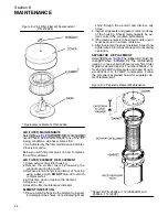
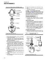
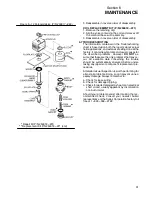
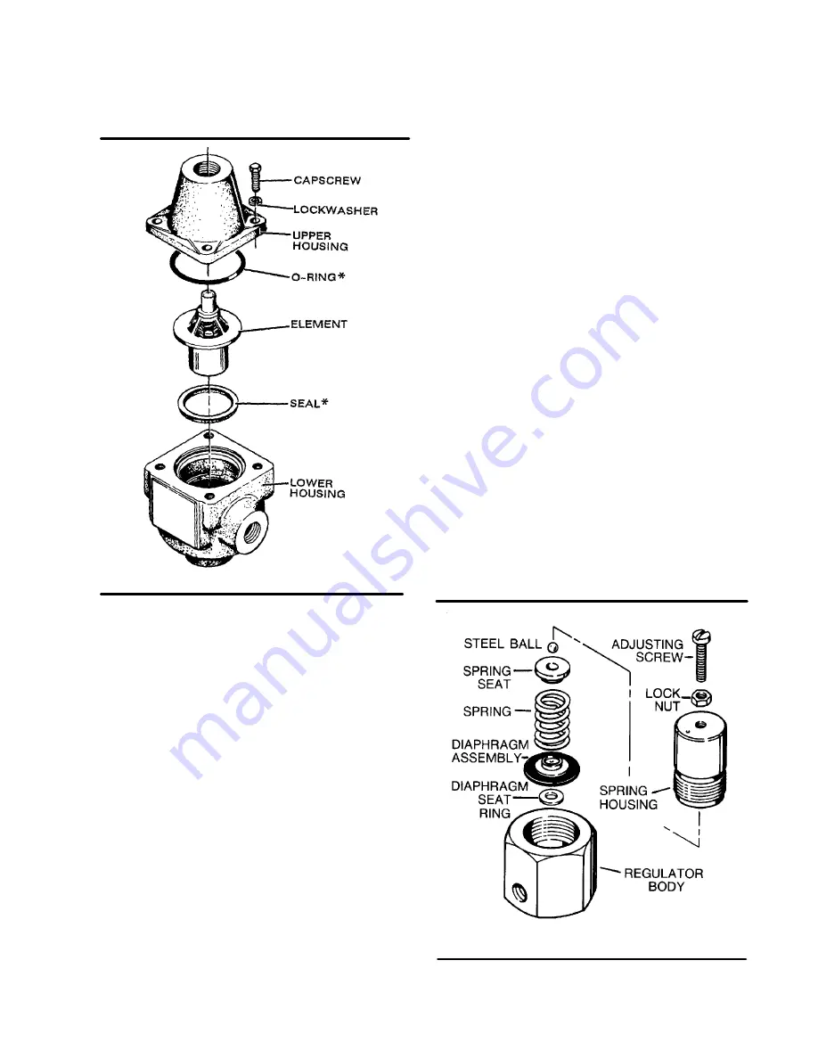
Figure 6---8 Thermal Valve (P/N 250025---620)
* Repair Kit P/N 250025---621
4. After removing the spring, remove the gasket
stop and brass gasket.
5. At this time, remove the pressure plate nut and
disassemble the pressure plate, diaphragm,
diaphragm gasket (rubberized asbestos), seat
disc and seat gasket.
6. Remove and discard the seat ring.
7. The next step is to reassemble the regulator us-
ing the new parts provided in the repair kit.
8. Reassemble the diaphragm, pressure plate,
gasket, seat disc, and seat disc gasket and
tighten the nut. All of these parts with the excep-
tion of the pressure plate are provided in the re-
pair kit.
9. Replace the seat ring with the new seat ring pro-
vided.
10. Replace the existing brass gasket and dia-
phragm gasket stop.
11. Next, place these parts in their proper place on
the body and replace the spring as it was prior to
disassembly.
12. Place the spring button, over the spring as
shown.
13. With all parts in order, replace the spring cham-
ber and tighten.
14. Tighten the adjusting screw until tension is real-
ized.
15. At this time, refer to Control System Adjustment
procedure and readjust.
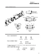
FLEXIBLE COUPLING MAINTENANCE
. Flexible coupling main te -
nance normally requires the replacement of the
(two) 2 gasket rings on the coupling. Select appro-
priate gasket rings from Table 3 and follow the pro-
cedure below for proper installation.
PIPE END PREPARATION
1. Deburr and clean the pipe ends.
2. The pipe ends should be free of all deep
scratches, gouges, dents, etc. A special finish is
not required.
JOINT INSTALLATION
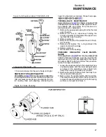
1. Install the retainer (1), gasket (2), and sleeve (3)
on one side of the pipe as shown in Step 1.
2. Install the remaining retainer (4) and gasket (5)
on the other pipe end.
3. Position the retainer (4) and gasket to proper
pipe insertion depth (“D”) as shown in Table 1.
4. Slide the sleeve (3) to the gasket (5) and move
gasket (2) and retainer (1) into position as
shown in Step 2. The pipe
MUST
be inserted to
the proper depth (“D”) into both gaskets.
COUPLER INSTALLATION
1. Install both V couplings as shown in Step 3, en-
compassing the retainer, gasket and sleeve.
DO
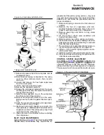
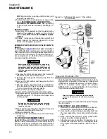
Figure 6---9 Pressure Regulator Valve
* Repair Kit P/N 250019---453
(P/N 250017---280)
*
*
Summary of Contents for 10B 25HP
Page 2: ...NOTE For Additional Information on 24KT Units See Inside Back Cover...
Page 4: ...NOTES...
Page 22: ...16 NOTES...
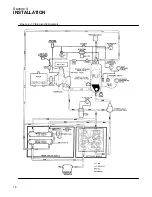
Page 24: ...Section 4 INSTALLATION 18 Figure 4 1 Piping and Instruments...
Page 26: ...20 NOTES...
Page 42: ...36 NOTES...
Page 44: ...NOTES...
Page 45: ......

