


Section 2
DESCRIPTION
6
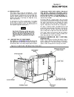
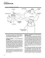
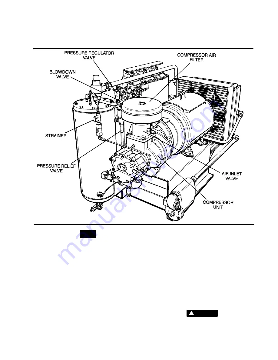
Figure 2---2 Sullair Series 10B Rotary Screw Compressor
NOTE
With a Sullair compressor, there is no mainte-
nance or internal inspection of the compressor
unit required.
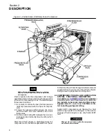
Fluid is injected into the compressor unit in large
quantities where it mixes directly with the air as the
rotors turn, compressing the air. The fluid flow has
three basic functions:
1. As coolant, it controls the rise of air temperature
normally associated with the heat of compres-
sion.
2. It seals the leakage paths between the rotors
and the stator and also between the rotors
themselves.
3. It acts as a lubricating film between the rotors al-
lowing one rotor to directly drive the other, which
is an idler.
After the air/fluid mixture is discharged from the
compressor unit, the fluid is separated from the air.
At this time, the air flows through an aftercooler and
separator then to your service line while the fluid is
being cooled in preparation for reinjection.
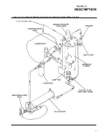
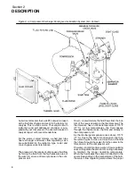
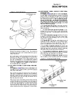
2.4 COMPRESSOR COOLING AND LUBRICATION
SYSTEM, FUNCTIONAL DESCRIPTION
Refer t o Figures
. The cooling a nd lu -
brication system (air---cooled version) consists of a
fan
,
radiator--type cooler
,
main line filter
,
cooler
bypass valve
(air---cooled only),
inlet filter
and
in-
terconnecting piping and tubing
.
Sullair 24KT compressors are filled with a fluid
which rarely needs to be changed. In the event a
change of fluid is required, use only Sullair 24KT
fluid.
WARNING
!
Mixing of other lubricants within the compressor
unit will void all warranties!
Summary of Contents for 10B 25HP
Page 2: ...NOTE For Additional Information on 24KT Units See Inside Back Cover...
Page 4: ...NOTES...
Page 22: ...16 NOTES...
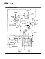
Page 24: ...Section 4 INSTALLATION 18 Figure 4 1 Piping and Instruments...
Page 26: ...20 NOTES...
Page 42: ...36 NOTES...
Page 44: ...NOTES...
Page 45: ......


