background image

Section 6

MAINTENANCE

26

ating pressure which is stamped on the compres-

sor serial number nameplate. The following expla-

nation applies to a typical installation with a desired

operating range of 115 to 125 PSIG (792 to

862kPa). This information will apply to a compres-

sor with any other operating range excepting the

stated pressures.
Remove the cover of the pressure switch, pressure

regulator and inlet valve as required. With the

shut---off valve closed (or slightly cracked open)

start the compressor. Observe the line pressure

gauge and pressure switch contacts. When the line

pressure reaches 125 PSIG (862kPa), the pressure

switch contacts should open. If the pressure switch

contacts do not open or they open prior to the de-

sired pressure, the pressure switch setting will re-

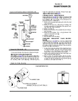
quire adjustment (refer to Figure 6---5).

FOR PRESSURE RANGE ADJUSTMENT

:

1. Remove cover to pressure switch.

2. Turn the range adjusting screw to the high pres-

sure setting. Turning the screw counterclock-

wise lowers both the high and low pressure

equally.

FOR DIFFERENTIAL ADJUSTMENT:

Differential is the difference between the high and

low pressure settings. 10 PSIG (7kPa) is typical.
1. Turn the differential adjusting screw to the lower

(reset) setting. Turning the screw counterclock-

wise widens the differential by lowering the reset

(lower) setting only.

2. When the pressure switch adjustment is com-

plete, the pressure regulator should be adjusted

for the pressure at which modulation of air deliv-

ery should begin. In this case that pressure will

be 118 PSIG (824kPa). The regulator is adjusted

by loosening the jam nut on the end of the cone

shaped cover of the pressure regulator. When

the jam nut is loose, turn the adjusting screw

clockwise to increase or counterclockwise to

decrease the setting.

3. To set the regulator, continue closing the service

valve, until the line pressure is 118 PSIG

(824kPa). At this point regulator should pass a

signal to the inlet valve to start closing it. If the

line pressure keeps on rising or if the modulation

does not begin, adjust the regulator valve as de-

scribed above. After adjustment line pressure

should be approximately 118 PSIG (824kPa)

and 1.00 in. Hg vacuum below the inlet.

4. Now close the service valve, line pressure will

start rising. When line pressure reaches 125

lbs., the inlet valve will be closed to its maximum

position. The inlet vacuum at this point will be

around 25 in. Hg. The machine should unload at

this point.

5. Open the service valve so the line pressure is 115

PSIG (792kPa). Machine is now set for opera-

tion. Recheck the unload pressure by closing of

the service valve. Machine should unload via the

pressure switch at 125 PSIG (862kPa).

After the control pressures have been adjusted, the

“unloaded” sump pressure should be checked. It

will be necessary to shut the compressor down, re-

move the pressure switch cover and disconnect

one of the two lead wires that are connected to the

micro---switch (contact block). After disconnecting

the lead, tape the exposed wire with electricians

tape to make sure that it does not come in contact

with any metallic surface.

DANGER

!

DO NOT touch the electrical contacts, terminal or

leads with any metallic object. Severe electrical

shock may occur.

With the lead taped, you may start the compressor

again. Allow the sump pressure to stabilize.
The sump pressure should read 30 to 35 PSIG (207

to 281kPa).
Once this is checked, shut the compressor down

once again and reconnect the taped lead and re-

place the pressure switch cover. At this time, start

the compressor and cycle the Control System sev-

eral times and re---check all pressure settings and

adjustments.

DANGER

!

DO NOT touch the pressure switch, electrical

contacts, terminal board or leads with any part of

the body or any uninsulated metallic object. Se-

vere electrical shock may occur.

Cycle the Control System several times and re-

check all pressure settings.

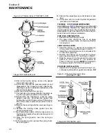
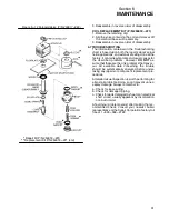
BLOWDOWN VALVE MAINTENANCE

Refer t o Figure 

6 --- 6

. Blow dow n va lve n o.

250025---655 maintenance is limited to replace-

ment o---rings and the teflon seat. Use repair kit no.

250031---772 and follow the instructions below for

proper installation.
1. Unscrew end caps from the valve body and re-

move.

2. Hold nut with an appropriate socket wrench and

turn screw until loose.

3. Next, remove all internal parts mounted on the

machine screw. Remove the old o---rings and te-

flon seat and discard.

4. Replace with the new o---rings and teflon seat

provided in the repair kit. Apply appropriate lu-

bricant to o---rings and valve body bore.

5. Pre---assemble the internal parts for pilot (P) side

of the valve onto the screw and install into the

body.

6. Assemble remaining internal parts for inlet (I)

side to the screw as illustrated. Once as-

sembled, install the locknut and torque to 25

in.---lbs. (2.82Nm).

Summary of Contents for 10B 25HP

Page 1: ...10B Open 25 30 40HP OPERATOR S MANUAL Part Number 02250049 581 eSullair Corporation AIR COMPRESSOR INDUSTRIAL STANDARD AND 24KT...

Page 2: ...NOTE For Additional Information on 24KT Units See Inside Back Cover...

Page 3: ...t Sullair s corporate headquarters in Michigan City Indiana Instruction includes discussion of the function and installation of Sullair service parts troubleshooting of the most common problems and ac...

Page 4: ...NOTES...

Page 5: ...NG AND LUBRICATION SYSTEM FUNCTIONAL DESCRIPTION 9 2 5 COMPRESSOR DISCHARGE SYSTEM FUNCTIONAL DESCRIPTION 9 2 6 CONTROL SYSTEM FUNCTIONAL DESCRIPTION 11 2 7 AIR INLET SYSTEM FUNCTIONAL DESCRIPTION 11...

Page 6: ...ARTS REPLACEMENT AND ADJUSTMENT PROCEDURES 23 FLUID FILTER ELEMENT REPLACEMENT 24 AIR FILTER MAINTENANCE 24 SEPARATOR REPLACMENT 25 INLET VALVE MAINTENANCE 25 CONTROL SYSTEM ADJUSTMENT 26 BLOWDOWN VAL...

Page 7: ...tle valve either at the compressor or at any other point along the air line when an air hose exceeding 2 13mm inside diameter is to be connected to the shut off throttle valve to reduce pressure in c...

Page 8: ...oved C Wear snug fitting clothing and confine long hair when working around this compressor especially when exposed to hot or moving parts D Keep access doors if any closed except when making repairs...

Page 9: ...ctors 1 9 LIFTING A If the compressor is provided with a lifting bail then lift by the bail provided If no bail is provided then lift by sling Compressors to be air lifted by helicopter must not be su...

Page 10: ...enter it to perform service adjustments inform other per sonnel before doing so or else secure and tag the access door in the open position to avoid the possi bility of others closing and possibly lat...

Page 11: ...cludes compressor electric motor starter compressor inlet system compressor discharge system compressor lubrication and cooling system ca pacity control system and instrumentation Op tional accessorie...

Page 12: ...or to directly drive the other which is an idler After the air fluid mixture is discharged from the compressor unit the fluid is separated from the air At this time the air flows through an aftercoole...

Page 13: ...Section 2 DESCRIPTION 7 Figure 2 3 Compressor Discharge Cooling and Lubrication System Water Cooled...

Page 14: ...a of the sump to an area of lower pressure in the com pressor unit On air cooled models the fluid flows from the bot tom of the receiver sump to the thermal valve The thermal valve has a nominal tempe...

Page 15: ...ion of the compressor in an unloaded condition A pressure relief valve located on the wet side of the separator is set to open if the sump pressure exceeds 200 PSIG 1379kPa A temperature switch will s...

Page 16: ...he inlet valve The ori fice also bleeds any accumulated moisture from the control lines UNLOAD IN EXCESS OF 125 PSIG 862kPa LINE PRESSURE When no air is being used the service line pressure rises to t...

Page 17: ...nstrumentation for the25 30 and 40HP air compressors consists of a panel group which continually monitors the operating condition of the compressor The panel group has the following gauges a sump pres...

Page 18: ...IPTION 12 when the element should be changed S When the compressor is tank mounted on either a 120 or a 200 gallon auxiliary air receiver an addi tional pressure gauge is supplied to monitor tank and...

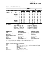
Page 19: ...27 004 40HP Air cooled 251334 004 40HP Water cooled 251328 004 24KT 25HP Air cooled 251335 003 25HP Water cooled 251329 003 30HP Air cooled 251336 003 30HP Water cooled 251330 003 40HP Air cooled 2513...

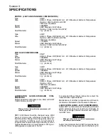
Page 20: ...able Speed 3000RPM Starter 380V Magnetic Full Voltage Shaft Diameter 1 8 41 3mm LUBRICATION GUIDE STANDARD COM PRESSORS Sullair standard compressors are filled with SRF 1 4000 fluid as factory fill WA...

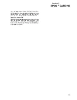
Page 21: ...ed with your compressor The user will re ceive an analysis report with recommendations APPLICATION GUIDE Sullair encourages the user to participate in a fluid analysis program with the fluid suppliers...

Page 22: ...16 NOTES...

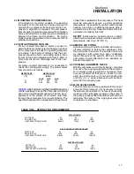
Page 23: ...e this heat for space heating providing no additional pressure drop is created across the fan Consult a Sullair office for assistance in utilizing this heat DO NOT install a water cooled or an air coo...

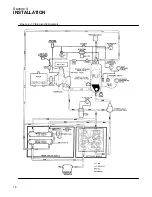
Page 24: ...Section 4 INSTALLATION 18 Figure 4 1 Piping and Instruments...

Page 25: ...with OSHA National Electrical Code and any other applicable local electrical code concerning isola tion switches fused disconnects etc Sullair pro vides a wiring diagram for use by the installer An e...

Page 26: ...20 NOTES...

Page 27: ...ent change is required SEPARATOR MAINTENANCE GAUGE Indicates when separator element change is re quired AIR FILTER MAINTENANCE INDICATOR Shows red when air filter element servicing is re quired This i...

Page 28: ...the water cooled only cooler to keep the compressor running at a normal operating temperature of 170_F 77_C 5 3 INITIAL START UP PROCEDURE The following procedure should be used to make the initial s...

Page 29: ...OURS OF OPERATION After the initial 50 hours of operation a few mainte nance requirements are needed to rid the system of any foreign materials Perform the following maintenance operations to prevent...

Page 30: ...ELEMENT INSPECTION 1 Place a bright light inside the element to inspect for damage or leak holes Concentrated light will shine through the element and disclose any holes 2 Inspect all gaskets and gask...

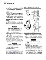
Page 31: ...aintenance may require the re placement of the piston spring piston o ring seal ring and check valve spring Use repair kit number 250019 451 and follow the procedure below for proper installation 1 Re...

Page 32: ...re reaches 125 lbs the inlet valve will be closed to its maximum position The inlet vacuum at this point will be around 25 in Hg The machine should unload at this point 5 Open the service valve so the...

Page 33: ...parate the upper hous ing from the lower housing 3 Remove element 4 Remove and replace the element seal in the up per housing 5 Remove and replace the o ring between the upper and lower housings 6 Rep...

Page 34: ...hten 14 Tighten the adjusting screw until tension is real ized 15 At this time refer to Control System Adjustment procedure and readjust FLEXIBLE COUPLING MAINTENANCE Refer to Figure 6 10 Flexible cou...

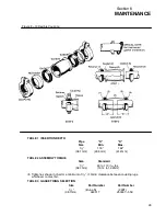
Page 35: ...62 38 1mm 29 5mm 41 2mm TABLE 2 ASSEMBLY TORQUE Size Standard 1 2 90 to 110 in lbs 38 1mm 10 14 to 12 4Nm I Tighten as shown in chart or a minimum of 16 1 5mm clearance between coupling lugs whichever...

Page 36: ...e seal ring and discard 6 Clean piston assembly and valve thoroughly 7 Replace seal ring and coat the piston and seal with Parker Super O Ring Seal or anequivalent quality grease WARNING Extreme cauti...

Page 37: ...ontains symptoms and usual causes for the described problems However DO NOT as sume that these are the only problems that may oc cur All available data concerning the trouble should be systematically...

Page 38: ...ust to 135 PSIG 931kPa Defective solenoid valve solenoid valve should cause control lever to move to unload stop when the pressure switch contacts open Repair if defective Defective blowdown valve blo...

Page 39: ...s are not damaged Replace if necessary Defective Solenoid Valve Repair kit available Defective Blowdown Valve Check that sump pressure is exhausted to the atmosphere when the pressure switch contacts...

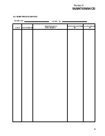
Page 40: ...Section 6 MAINTENANCE 34 MODEL NO SERIAL NO 6 8 MAINTENANCE RECORD DATE HOURMETER MAINTENANCE PERFORMED WORK PERFORMED BY AUTHORIZED BY...

Page 41: ...Section 6 MAINTENANCE 35 MODEL NO SERIAL NO 6 8 MAINTENANCE RECORD DATE HOURMETER MAINTENANCE PERFORMED WORK PERFORMED BY AUTHORIZED BY...

Page 42: ...36 NOTES...

Page 43: ...n fluid filter 250025 521 250025 525 std 24KT 2 repair kit for separator element 25 30HP 250034 111 250034 112 std 1 250034 114 24KT 1 repair kit for separator element 40HP 250034 113 250034 114 std 2...

Page 44: ...NOTES...

Page 45: ......

Page 46: ...pecifications Subject To Change Without Prior Notice WORLDWIDE SALES AND SERVICE SULLAIR CORPORATION 3700 E Michigan Blvd Michigan City Indiana 46360 9990 Telephone 219 879 5451 A SUBSIDIARY OF SUNDST...

Reviews: