background image

DCX.Server/DCX.Client/DCX.NC 


www.stute-engineering.de


C

h

a

p

ter

So

ft

wa

re de

scri

p

tio

n


1
0


3


Software description 

3.1


DCX.Server 

Note: To use the software without the DEMO limits your DCX.Server software license must 
activated. You find more details t the topic in chapter 6. 

Attention: Do not connect or disconnect the USB-RS232 interface when the DCX.Server is 
running 

Attention: Do not quit the DCX.Server software or switch off the DCX.Server computer during 
an established connection to the DCX.Client! 


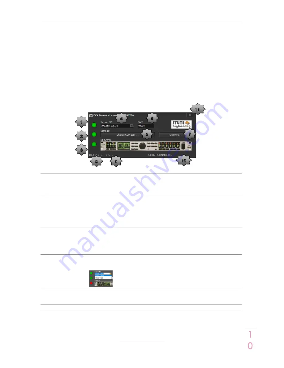
LED Network connection status 
Green
: Connected to the DCX.Client 
Yellow: Not connected to the client 
Red: Network issues 

RS232 Port: Press the button, to select 
the RS232/COM port for the USB-RS232 
interface. The current port number is 
displayed above of the button 

LED RS232 interface status 
Green
: Displayed RS232 port (e.g. 
COM10) successful opened  
Yellow: Searching DCX2496 devices 
Red: Displayed COM port not found or 
in use via another software 

Password protection for the settings: 
Server IP, Port and COM port. Set the 
password and re-start DCX.Server. 
Reset the password via a two times 
“blank” input. 

LED DCX2496 communication status 
Green
: Successfully connected with the 
DCX2496 device 
Red: DCX currently not connected 
/DCX powered off.  

DCX2496 Device Id: DCX.Server is 
currently connected to the displayed 
DCX device Id 

Server IP address 
Must be a valid address of your local 
network. Otherwise select the correct 

one from the list 


Name of the DCX.Client: Connected 
currently with the displayed DCX.Client 
name (name from the client software 
“Settings” and “User name”) 

Port number. Default 40000. Must be 
identical to the port from the client 
software 

10 

Status messages: Notifications and 
error messages 


11 

Quit the program 


Note: The LED “Network” and “RS232” flashes during the communication. 


Summary of Contents for DCX.CLIENT

Page 1: ...DCX Server DCX Client DCX NC www stute engineering de Chapter Introduction 1 ID EN5218A DCX SCN EN DCX SERVER DCX CLIENT DCX NC ...

Page 2: ...e DCX Client on multiple devices e g computer and tablet 5 1 11 Is it possible to execute the DCX Server on a Wi Fi connected computer 5 2 Quick Start 6 2 1 Note Demo Test Mode 6 2 2 Software installation 6 2 2 1 DCX Server full version and trail 6 2 2 2 DCX Client 6 2 3 Program screens 7 2 4 Prepare your DCX2496 device 7 2 5 Firewall network communication 7 2 6 BASIC configuration DCX Server DCX ...

Page 3: ...ors 24 5 2 LAN connection 24 5 3 Software update controller DCX NC 25 6 Software license key DCX Server 25 7 FAQ 26 7 1 DCX Server 26 7 2 DCX Client 26 7 2 1 Messages footer 26 7 2 2 DCX2496 values Gain threshold frequency 27 7 2 3 Network App 27 7 2 4 With DCX NC controller 28 7 3 DCX NC 28 7 3 1 Power supply 28 7 3 2 Network 28 8 System requirements 29 8 1 DCX Server software 29 8 2 DCX Client s...

Page 4: ... computer or PC 1 2 How does it work The system contains two software products The DCX Client software provides the user interface for DCX2496 remote control like gain volume slider or mute switches The client will be installed at your mobile phone tablet or laptop The DCX Server software is installed at a second PC and receives via Wi Fi the DCX Client commands The commands are translated and via...

Page 5: ... Level from In A B C Output 1 6 o Level Mute Delay long short o EQ 1 9 Dynamic EQ o X Over incl X Over link Phase Polarity Limiter DCX2496 Setup o Adjustment Out configuration MONO LMH LMH o Adjustment In Stereo Link A B o Adjustment Sum signal setup A B A B C o Adjustment Output source for Out 1 6 A B C Sum Note Delay Link is not supported and should be switched off 1 9 Is it possible to store re...

Page 6: ...etup file from out homepage see Download Open the setup file to start the installation Follow the displayed messages from the setup screen 2 2 2 DCX Client 2 2 2 1 macOS Download the setup file PKG from out homepage see Download Open the DCXClient PKG package file to start the installation Follow the displayed messages from the setup screen Note Enable System Preferences Security Privacy Allow app...

Page 7: ...ge SETUP Miscellaneous o Select Port and set PC RS232 via the DCX2496 data wheel to control a single DCX2496 device o Settings for a DCX2496 device cluster see chapter 4 Press the SETUP button to store the changes 2 5 Firewall network communication Important Allow the network communication between the software DCX Server and DCX Client via your firewall During the operation the firewall recognize ...

Page 8: ... software at your computer or tablet mobile phone see chapter 2 2 Open the program DCX Client DCX Server should already started o For the first start wait 20 30 seconds The client searches for the DCX Server Note Via the button Find DCX Server NC from the Settings Network tab you check the network connection to the DCX Server 2 6 2 Control your DCX2496 device Follow the chapter First steps Switch ...

Page 9: ...obile phone see chapter 2 2 Open the program DCX Client o For the first start wait 20 30 seconds The client searches for the DCX NC Note Test the network connection to the DCX NC server via the button Check DCX Server from the tab Settings 2 7 2 Control your DCX2496 device Pre condition DCX2496 device and DCX NC controller are switched on Open the DCX Client e g from your mobile phone o Select the...

Page 10: ...Green Displayed RS232 port e g COM10 successful opened Yellow Searching DCX2496 devices Red Displayed COM port not found or in use via another software 7 Password protection for the settings Server IP Port and COM port Set the password and re start DCX Server Reset the password via a two times blank input 3 LED DCX2496 communication status Green Successfully connected with the DCX2496 device Red D...

Page 11: ...r 3 2 7 Note Depending at the selected tab all or some buttons are disabled 4 Footer status bar for notifications plus a color coded status panel Green Notes no issues Yellow Action needed Red Issue read the displayed message 5 Footer status bar Displays for the selected output star 3 the input source and output name 6 Progress bar Display the status for a The import of the DCX2496 settings after ...

Page 12: ...stablish the connection to the DCX2496 device with the selected Id and import the DCX2496 settings Gain EQ X Over Note The progress bar in the footer displays the progress 4 DCX2496 input and output configuration On Output configuration enabled Off Disabled Note Changes are affected a channel combination With In A B C Sum a change of the volume In A level changes also the In B C and Sum gain You f...

Page 13: ...el adjusts other inputs synchronously 2 3 Input Sum B C Control the Sum output and inputs gain see note Change the gain similar as described in star 1 If the viewed channel from star 3 is a Out You control the Sum output gain with the slider b In A or B or C You control the Input gain of In A or B or C of the Sum signal Note The Sum channel includes the signal from the displayed inputs in the pict...

Page 14: ...Equalizer EQ View and control the settings for the equalizer Note Star 6 settings are disabled EQ Dyn View and control the settings for the dynamic equalizer Note Star 4 EQ number is disabled 3 Switch EQ Dyn EQ on off Switch the EQ or EQ Dyn on or off depends from star 2 4 EQ number Note Only enabled for EQ see star 2 Choose the EQ number 1 9 The green number indicates the currently selected EQ nu...

Page 15: ...ut off frequency via the slider or buttons Set Upper frequency from previous channel as lower E g LMH out config M Lower L Upper 3 Upper cut off Band or Low pass Band pass Lower and Upper filter type NOT off Type Select a filter type from the list e g L R 12 or Bessel 24 Frequency Adjust the cut off frequency via the slider or buttons 4 Link X Over link On or Off see device manual DCX2496 Note Set...

Page 16: ...t 1 6 A B C S are disabled The displayed settings and changes affects to the selected channel The green channel number text indicates the currently selected channel 2 Limiter Set the limiter parameter Threshold and Release Adjust the values via the slider or buttons The switch Limiter On enables disables the Limiter for the selected channel 3 Phase Out Set phase value via the slider or buttons for...

Page 17: ...e RS232 and network data traffic Note A step size different to 0 1dB DCX2496 standard displays rounded values after the first reading of the DCX2496 settings E g IN A gain 12 3 will display as 12 5dB with a step size from 0 5 2 User Enter an unique user name for each client The name is displayed at DCX Server as an indicator who controls currently the DCX2496 3 Screen rotation 180 only for Android...

Page 18: ...ar for Out 4 to 6 For this configuration channel 1 4 2 5 3 6 are linked Changes at one channel are automatically transferred to the linked channel Note Details see DCX2496 manual 3 In Stereo Adjust the DCX2496 input stereo link e g A B changes at Input A are automatically transferred to Input B 4 In Sum Set source signals for SUM signal e g A B Sum Input A B 5 Source Output Set source for each out...

Page 19: ...rt value Must be identical with the value from the DCX Server default 40000 3 Find DCX Server NC Button executes a network request to find the IP address of the DCX Server DCX NC 4 Display the DCX Server NC software version 5 Shutdown Remote shutdown of the computer where the DCX Server incl DCX NC is executed Attention A shutdown command quit the DCX Server MS Windows system Not saved data from o...

Page 20: ...Read and Shut down The password is set when both password entries Password and Password confirmation are the same and the text Password lit green 2 Change Press the button Change to set or erase an existing password Erase the password input via a two times blank password entry Change an existing password Enter first the existing password Afterwards enter the new password ...

Page 21: ...to 5dB 2 Press the button to the store the last change 3 Adjust the same parameter to another value like gain level Out 2 to 2dB 4 Press the button to recall the stored value from step 2 for the example gain level out 2 is set to 5dB 5 Press the button again to recall the previous value from step 3 for the example gain level out 2 is set to 2dB 6 Each repeated press switches between the two values...

Page 22: ...X2496 device Connect the USB RS232 interface with the RS232 connector from the DCX2496 rear side DCX2496 adjust SETUP Miscellaneous o Set Port PC RS232 4 2 Control two DCX2496 devices First DCX Connect the USB RS232 interface with the RS232 plug of the DCX2496 rear side Adjust SETUP Miscellaneous o Set Port PC Link Enable Push the RS485 Term button from the DCX2496 rear side Second DCX Connect the...

Page 23: ...the DCX2496 rear side Second DCX Connect the 2nd DCX2496 with the first DCX via the RS485 connector Adjust SETUP Miscellaneous o Set Port LINK RS485 Set the Device Id different to the Id from the first DCX2496 o E g Device ID 2 Disable the RS485 Term button from the DCX2496 rear side Last DCX Connect the 3rd DCX2496 with the 2nd DCX via the RS485 connector Adjust SETUP Miscellaneous o Set Port LIN...

Page 24: ... DCX Client In error cases hold the button until the blue led is switched off 2 Power supply connector Connect the delivered power supply with the connector 3 USB port Connect the delivered USB RS232 interface with this port 4 HDMI output optional Not used 5 LAN network interface plug for a LAN cable 6 Additional USB ports Not used Attention Do not switch off the controller during an established c...

Page 25: ...Server Update program icon Otherwise send the controller to Stute Engineering for maintenance 6 Software license key DCX Server Without a valid software license key the DCX Server software runs in the TRAIL mode The limits are The DCX Client controls only the Inputs A C of your DCX2496 Order via the license assistant your key Note The DCX Client MS Windows macOS iOS Android is free of charge and n...

Page 26: ...t 7 2 1 Messages footer DCX Server NC offline DCX Server not found DCX Server DCX NC not started or firewall network issues Check the firewall settings Allow the communication Check Is at your tablet mobile phone Wi Fi deactivated DCX Server PC needs a wired LAN connection See also chapter 7 2 3 DCX2496 RS232 interface not connected DCX2496 switched off or USB RS232 interface not connected to the ...

Page 27: ...wer the frequency higher from channel 1 Output configuration LMH LMH DCX2496 X Over Link function enabled see DCX2496 manual Disable the function with the client tab X Over switch Link Tab X Over Text color Lower and Upper cut off is red Band pass mode upper lower filter type not off Invalid value lower frequency upper frequency Change lower or upper Tab X Over Gain value changes from channel 1 ar...

Page 28: ...CX NC Network connection not possible Shut down and re start the DCX NC See chapter 5 7 3 DCX NC 7 3 1 Power supply Blue LED at the front is off Check the power supply power supply connection Blue LED at the front is off Switch the DCX NC controller on at the rear side How to power off the DCX NC Switch off the DCX NC via the client Tab Settings button Shutdown 7 3 2 Network IP address of the DCX ...

Page 29: ...perating system OS X El Capitan or higher 8 2 3 Android Note Use syscheck from the Google app store to check the requirements Operating system Android 5 or higher CPU Cortex A Series ARM64 NEON technology supported Screen min 680x360pixel 8 2 4 iOS Operating system iOS 9 or higher iPhone 6 or higher 8 3 DCX NC Power supply 110Vac 240Vac 50Hz 60Hz Ethernet network connection RJ45 100Mbit or 1000Mbi...

Reviews: