background image

47

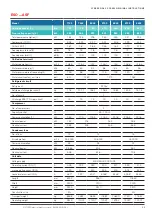
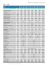
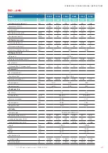
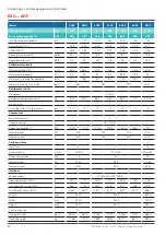
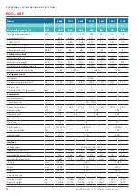
EQO ... AHF

Modell

3002

3302

3702

4002

4702

5102

6002

Kühlleistung (1)

kW

333

357

375

398

498

523

598

Kühlleistung Freie Kühlung (4)

kW

345

354

360

367

490

499

520

Gesamtaufnahmeleistung (1)

kW

80

86

92

98

121

131

149

Kompressor COP (1)

4,61

4,56

4,45

4,42

4,52

4,36

4,31

Geräte EER (1)

4,16

4,15

4,08

4,07

4,12

4

4

Schalldruckpegel (2)

dB(A)

68

70

70

70

71

71

71

Schallleistungspegel (3)

dB(A)

91

91

91

91

93

93

93

Kaltwasserkreislauf

Wasservolumenstrom (1)

m³/h

47,7

51,2

53,7

57,1

71,4

75

85,7

Wasserdruckverlust (1)

kPa

69

76

58

62

52

54

52

Wasserdruckverlust freie Kühlung (4)

kPa

94

103

86

91

79

82

83

Wasserkreislaufvolumen, geräteseitig

dm³

716

713

1016

1053

Kältekreislauf

Kältemittel

R134a

Kältemittelfüllmenge (pro Kreislauf)

kg

73,7

76

74,1

76,4

105,7

117,3

114,7

Anzahl Kältekreisläufe

2

Ölfüllmenge BSE170-L (pro Kreislauf)

dm³

15

15

15

15

15

15

22

Kompressor

Anzahl Kompressoren

2

Leistungsregelung

%

25 - 100 %

Aufnahmeleistung (1)

kW

72,2

78,4

84,2

90,1

110,2

119,9

138,6

Nennleistung

kW

94

110

144

174

Nennstrom

A

168

196

256

312

Ventilatoren

Anzahl Ventilatoren

10

14

Luftvolumenstrom

m³/h

160.000

224.000

Aufnahmeleistung

kW

8,1

11,3

Nennleistung

kW

28,8

40,3

Nennstrom

A

44

61,6

Gerätedaten

Spannungsversorgung

400V/50Hz/3Ph/N/PE

Betriebsstrom (OA) (1)

A

143

153

157

166

207

218

261

maximaler Betriebsstrom (RLA)

A

272

289

298

317

404

422

488

Kurzschlussstrom (LRA)

A

427*

432*

507*

512*

628*

633*

804*

Länge

mm

7250

9480

Breite

mm

2300

2300

Höhe

mm

2510

2510

Baugröße

2

3

Transportgewicht

kg

7047

7142

7131

7226

9280

9443

10927

Betriebsgewicht

kg

7794

7889

7875

7970

10339

10502

12026

 © STULZ GmbH – all rights reserved EN/09.2019/G41

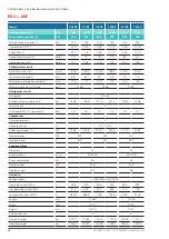
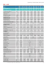
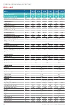
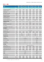
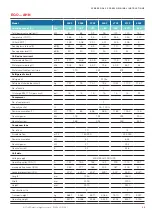
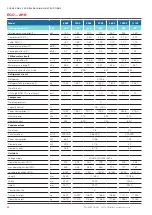
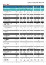
cybercool 2 screw original insTrUcTions

Model

Cooling capacity (1)

kW

Free cooling capacity (4)

kW

Total power consumption (1)

kW

Compressor COP (1)

Chiller EER (1)

Sound pressure level (2)

dB(A)

Sound power level (3)

dB(A)

Chilled water circuit

Water volume flow (1)

m³/h

Water pressure drop (1)

kPa

Water pressure drop free cooling (4)

kPa

Water circuit content, unit side

dm³

Refrigerant circuit

Refrigerant

Refrigerant charge (per circuit)

kg

No. of circuits

Oil charge BSE170-L (per circuit)

dm³

Compressor

No. of compressors

Capacity control

%

Power consumption (1)

kW

Nominal power

kW

Nominal current

A

Condenser fans

No. of fans

Air volume flow

m³/h

Power consumption

kW

Nominal power

kW

Nominal current

A

unit data

Voltage supply

Operating current (OA) (1)

A

max operating current (RLA)

A

Locked rotor current (LRA)

A

Length

mm

Width

mm

Height

mm

Construction size

Transport weight

kg

Operating weight

kg

Summary of Contents for CyberCool 2

Page 1: ...CyberCool 2 Original instructions Precision Chillers Screw compressor 400V 50Hz 3Ph N PE Index G41 Issue 9 2019...

Page 2: ...g technology business spe cialising in A C for data centres and telecommunications installations STULZ has ten production plants 2 in Germany Italy the USA Great Britain Spain 2 in China Brazil and In...

Page 3: ...erfrom STULZ The units which were produced in Hamburg have been developed especiallyfor use in Data Cen ters and industry and satisfy all requirements for efficiency and reliability For general inquir...

Page 4: ...4 4 EN 09 2019 G41 STULZ GmbH all rights reserved CYBERCOOL 2 SCREW ORIGINAL INSTRUCTIONS...

Page 5: ...s on the supports 53 5 3 External water circuit 60 5 4 Electrical connection 64 6 Commissioning 68 6 1 Filling ofthe water circuit 68 6 2 Control ofthe electrical box 70 6 3 Control of pressure switch...

Page 6: ...ently available at the place where the system is used danger Works have to be carried out by competent staff only Safety devices may not be bypassed 1 3 Handling refrigerants Get qualified refrigerati...

Page 7: ...protocol must be kept b To be stored in the proximity ofthe unit c Access for competent staff in case of repairs and repeated inspection must be ensured Repeated inspection according to EN 378 The op...

Page 8: ...ions must be checked country specifically notice When delivery is accepted check the unit against the consignment papers for completeness and for external damage and record it on the consignment paper...

Page 9: ...unted at the base frame where the ropes belts must be attached The number of lifting lugs varies according to the construction size The lifting device must consist oftwo cross beams The drawings on th...

Page 10: ...4602 AHN 2525 5613 ESO 4302 AHF 2680 6480 ESO 4602 AHF 2681 6512 min 2300 max 2400 min 6000 EN 09 2019 G41 STULZ GmbH all rights reserved cybercool 2 screw original INSTRUCTIONS Construction size 1 T...

Page 11: ...010 5982 EQO 3702 A N 2970 5971 EQO 4002 A N 3010 6066 EQO 3002 ASF 3200 7018 EQO 3302 ASF 3230 7103 EQO 3702 ASF 3180 7102 EQO 4002 ASF 3220 7197 EQO 3002 AHF 3200 7047 EQO 3302 AHF 3230 7142 EQO 370...

Page 12: ...58 ESO 6702 AHN 3170 7194 ESO 7102 AHN 3170 7265 ESO 6702 AHF 3382 8548 ESO 7102 AHF 3382 8619 EN 09 2019 G41 STULZ GmbH all rights reserved cybercool 2 screw original INSTRUCTIONS Construction size 2...

Page 13: ...257 EQO 6602 A N 2720 9437 EQO 4702 ASF 3470 9233 EQO 5102 ASF 3520 9396 EQO 6002 ASF 2970 10880 EQO 6602 ASF 3010 11070 EQO 4702 AHF 3470 9280 EQO 5102 AHF 3520 9443 EQO 6002 AHF 2970 10927 EQO 6602...

Page 14: ...87 ESO 9802 AHN 3766 9739 ESO 9702 AHF 4049 11569 ESO 9802 AHF 4052 11721 min 6000 min 2300 max 2400 EN 09 2019 G41 STULZ GmbH all rights reserved cybercool 2 screw original INSTRUCTIONS Construction...

Page 15: ...N 4170 10665 EQO 9602 A N 4240 10865 EQO 7402 ASF 4570 12489 EQO 8002 ASF 4630 12695 EQO 8702 ASF 4550 12727 EQO 9602 ASF 4620 12927 EQO 7402 AHF 4570 12553 EQO 8002 AHF 4630 12749 EQO 8702 AHF 4550 1...

Page 16: ...1632 EQO 10202 ASF 5100 13803 EQO 11102 ASF 5030 14022 EQO 10202 AHF 5100 13874 EQO 11102 AHF 5030 14093 min 6000 min 2300 max 2400 EN 09 2019 G41 STULZ GmbH all rights reserved cybercool 2 screw orig...

Page 17: ...otection grille the protection grilles must be unscrewed to remove the polypropylene plates Remove these plates before start up Coil protection grille optional housing protection grille optional Optio...

Page 18: ...bar Temperatur min max Temperature min max Temp rature min max 10 100 C R134a 0098 E S O 740 2 A S F EN 09 2019 G41 STULZ GmbH all rights reserved cybercool 2 screw original INSTRUCTIONS Free cooling...

Page 19: ...construction sizes can be seen on pages 49 50 The side on which the electric cabinet is located is named front side in these operating instructions The compressors are installed one upon the other in...

Page 20: ...illers with screw compressors has a unit designation which takes the follow ing pattern ESO _ _ _ _ 2 ASN There are three more versions which can be combined among each other in anyway 1 Free cooling...

Page 21: ...ing functions Monitoring of motor coil temperature PTC Monitoring of rotating direction Monitoring of oil temperature PTC Restart interlock in case of malfunction The compressor cabinet is cooled by a...

Page 22: ...oling In units with free cooling exists an additional sensorforthe chilled watertemperature which is measured at the free cool ing coil outlet Airtemperatures electric cabinet inside temperature compr...

Page 23: ...tric network or UPS system must be grounded neutral wye the voltage distortions must be within the limits stated below and no inadmissibly high DC voltage portions may exist transient peak over voltag...

Page 24: ...60 Modellreihe ESO ASF 2 7102 7402 8002 8702 9602 9702 9802 Max Au entemperatur a C 42 0 43 3 42 3 41 0 39 6 42 8 41 6 max Wasservolumenstom b m h 164 176 184 206 221 211 225 min Wasservolumenstom c m...

Page 25: ...sservolumenstom c m h 119 126 134 143 152 160 Modellreihe ESO AHF 2 7102 7402 8002 8702 9602 9702 9802 Max Au entemperatur a C 56 4 58 9 56 7 57 6 55 1 59 2 57 0 max Wasservolumenstom b m h 165 177 18...

Page 26: ...9 max Wasservolumenstom b m h 142 171 180 195 209 223 236 min Wasservolumenstom c m h 67 80 85 91 98 104 111 Modellreihe EQO AHF 2 3002 3302 3702 4002 4702 5102 6002 Max Au entemperatur a C 60 0 60 0...

Page 27: ...l 7 0 7 5 Chloride content mg l 100 Chloride content with austenitic steels mg l 50 Free chlorine mg l 0 05 Hydrogen sulphide mg l 0 05 Ammonia NH3 NH4 mg l 0 05 Sulphate mg l 100 Manganese mg l 0 05...

Page 28: ...ound pressure level full load in 1m distance underfree field conditions according to ISO 3744 3 Sound power level full load underfree field conditions according to ISO 3744 4 Water inlet temperature 1...

Page 29: ...8 4 Ger tedaten Spannungsversorgung 400V 50Hz 3Ph N PE Betriebsstrom OA 1 A 185 194 209 216 254 264 284 maximaler Betriebsstrom RLA A 236 247 272 282 318 327 361 Kurzschlussstrom LRA A 390 395 464 467...

Page 30: ...strom A 38 4 44 8 51 2 Ger tedaten Spannungsversorgung 400V 50Hz 3Ph N PE Betriebsstrom OA 1 A 297 323 333 391 412 383 402 maximaler Betriebsstrom RLA A 375 414 427 479 498 485 504 Kurzschlussstrom LR...

Page 31: ...tedaten Spannungsversorgung 400V 50Hz 3Ph N PE Betriebsstrom OA 1 A 437 450 494 516 572 590 maximaler Betriebsstrom RLA A 548 566 601 623 693 711 Kurzschlussstrom LRA A 668 675 725 737 888 898 L nge...

Page 32: ...34 56 Nennstrom A 35 2 44 52 8 Ger tedaten Spannungsversorgung 400V 50Hz 3Ph N PE Betriebsstrom OA 1 A 190 199 216 222 261 270 292 maximaler Betriebsstrom RLA A 246 257 284 294 330 339 376 Kurzschluss...

Page 33: ...W 34 56 40 3 46 1 Nennstrom A 52 8 61 6 70 4 Ger tedaten Spannungsversorgung 400V 50Hz 3Ph N PE Betriebsstrom OA 1 A 305 332 342 400 421 393 412 maximaler Betriebsstrom RLA A 390 431 443 495 515 504 5...

Page 34: ...7 6 Nennstrom A 79 2 88 Ger tedaten Spannungsversorgung 400V 50Hz 3Ph N PE Betriebsstrom OA 1 A 448 462 505 527 585 602 maximaler Betriebsstrom RLA A 570 587 623 645 717 735 Kurzschlussstrom LRA A 682...

Page 35: ...32 38 4 Ger tedaten Spannungsversorgung 400V 50Hz 3Ph N PE Betriebsstrom OA 1 A 192 207 219 230 277 297 298 maximaler Betriebsstrom RLA A 318 343 374 392 459 490 516 Kurzschlussstrom LRA A 583 591 63...

Page 36: ...om A 38 4 44 8 51 2 Ger tedaten Spannungsversorgung 400V 50Hz 3Ph N PE Betriebsstrom OA 1 A 325 361 382 401 436 396 428 maximaler Betriebsstrom RLA A 560 595 632 632 692 639 698 Kurzschlussstrom LRA A...

Page 37: ...edaten Spannungsversorgung 400V 50Hz 3Ph N PE Betriebsstrom OA 1 A 451 481 514 554 571 610 maximaler Betriebsstrom RLA A 731 775 814 861 913 953 Kurzschlussstrom LRA A 892 907 1076 1097 1107 1128 L ng...

Page 38: ...W 23 04 28 8 34 56 Nennstrom A 35 2 44 0 52 8 Ger tedaten Spannungsversorgung 400V 50Hz 3Ph N PE Betriebsstrom OA 1 A 197 212 225 237 286 305 306 maximaler Betriebsstrom RLA A 328 353 386 404 471 502...

Page 39: ...tung kW 34 56 40 3 46 1 Nennstrom A 52 8 61 6 70 4 Ger tedaten Spannungsversorgung 400V 50Hz 3Ph N PE Betriebsstrom OA 1 A 333 370 392 410 445 406 438 maximaler Betriebsstrom RLA A 574 612 649 649 708...

Page 40: ...57 6 Nennstrom A 79 2 88 Ger tedaten Spannungsversorgung 400V 50Hz 3Ph N PE Betriebsstrom OA 1 A 463 492 525 565 583 622 maximaler Betriebsstrom RLA A 752 796 836 882 937 977 Kurzschlussstrom LRA A 90...

Page 41: ...8 Ger tedaten Spannungsversorgung 400V 50Hz 3Ph N PE Betriebsstrom OA 1 A 121 124 150 154 191 197 232 maximaler Betriebsstrom RLA A 191 197 218 225 285 295 330 Kurzschlussstrom LRA A 283 284 346 348 4...

Page 42: ...m A 44 8 57 6 64 Ger tedaten Spannungsversorgung 400V 50Hz 3Ph N PE Betriebsstrom OA 1 A 240 299 308 363 383 414 432 maximaler Betriebsstrom RLA A 340 427 439 491 511 555 572 Kurzschlussstrom LRA A 56...

Page 43: ...Nennleistung kW 28 8 40 3 Nennstrom A 44 61 6 Ger tedaten Spannungsversorgung 400V 50Hz 3Ph N PE Betriebsstrom OA 1 A 124 127 152 157 195 201 236 maximaler Betriebsstrom RLA A 203 209 230 237 302 311...

Page 44: ...2 Nennleistung kW 40 3 51 8 57 6 Nennstrom A 61 6 79 2 88 Ger tedaten Spannungsversorgung 400V 50Hz 3Ph N PE Betriebsstrom OA 1 A 244 304 313 368 388 420 438 maximaler Betriebsstrom RLA A 357 449 461...

Page 45: ...2 44 8 Ger tedaten Spannungsversorgung 400V 50Hz 3Ph N PE Betriebsstrom OA 1 A 140 150 154 163 203 214 257 maximaler Betriebsstrom RLA A 260 277 286 305 387 405 471 Kurzschlussstrom LRA A 424 429 504...

Page 46: ...nstrom A 44 8 57 6 64 Ger tedaten Spannungsversorgung 400V 50Hz 3Ph N PE Betriebsstrom OA 1 A 276 338 361 375 412 428 464 maximaler Betriebsstrom RLA A 502 608 645 645 704 737 781 Kurzschlussstrom LRA...

Page 47: ...8 8 40 3 Nennstrom A 44 61 6 Ger tedaten Spannungsversorgung 400V 50Hz 3Ph N PE Betriebsstrom OA 1 A 143 153 157 166 207 218 261 maximaler Betriebsstrom RLA A 272 289 298 317 404 422 488 Kurzschlussst...

Page 48: ...kW 40 3 51 8 57 6 Nennstrom A 61 6 79 2 88 Ger tedaten Spannungsversorgung 400V 50Hz 3Ph N PE Betriebsstrom OA 1 A 280 343 366 381 417 434 470 maximaler Betriebsstrom RLA A 519 629 667 667 726 761 80...

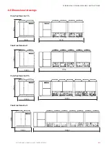
Page 49: ...8330 2300 2510 2300 2510 2300 2510 STULZ GmbH all rights reserved EN 09 2019 G41 cybercool 2 screw original INSTRUCTIONS 4 3 Dimensional drawings Construction size 2 Construction size 3 Construction...

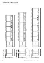
Page 50: ...50 11640 12785 2300 2510 10560 2300 2510 2300 2510 EN 09 2019 G41 STULZ GmbH all rights reserved cybercool 2 screw original INSTRUCTIONS Construction size 4 Construction size 5 Construction size 3...

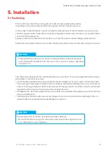
Page 51: ...by aerodynamically disadvantageous conditions 5 Installation 5 1 Positioning The fins ofthe air cooled free cooling coils are made of a high quality aluminum alloy Depending on the site an extended pr...

Page 52: ...original INSTRUCTIONS Maintenance clearance Space needed for individual installation and multiple unit installation Take into account the necessary clearances forthe maintenance and the airflow Keep a...

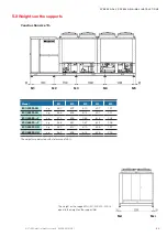
Page 53: ...834 306 ESO 4302 AHN kg 563 812 812 606 197 ESO 4602 AHN kg 559 806 815 626 200 M1 M2 M3 M4 M5 STULZ GmbH all rights reserved EN 09 2019 G41 cybercool 2 screw original INSTRUCTIONS 5 2 Weights on the...

Page 54: ...N kg 522 709 780 838 287 EQO 3302 A N kg 522 716 799 856 289 EQO 3702 A N kg 528 719 790 848 291 EQO 4002 A N kg 529 727 810 866 294 EQO 3002 A F kg 539 810 994 1052 503 EQO 3302 A F kg 540 818 1013 1...

Page 55: ...96 960 907 849 343 ESO 6702 AHN kg 695 894 754 651 621 233 ESO 7102 AHN kg 688 896 781 674 614 227 Mxl Mxr M1 M2 M3 M4 M5 M6 STULZ GmbH all rights reserved EN 09 2019 G41 cybercool 2 screw original IN...

Page 56: ...5 770 801 879 757 260 EQO 5102 A N kg 586 781 833 906 765 264 EQO 6002 A N kg 828 971 952 993 862 290 EQO 6602 A N kg 829 983 985 1021 870 295 EQO 4702 A F kg 696 988 980 1014 980 513 EQO 5102 A F kg...

Page 57: ...ESO 9802 A F kg 862 1235 1160 1092 996 830 392 ESO 9702 AHN kg 844 1135 939 767 705 553 250 ESO 9802 AHN kg 842 1135 958 822 719 548 249 Mxl Mxr STULZ GmbH all rights reserved EN 09 2019 G41 cybercool...

Page 58: ...58 987 940 965 1016 757 209 EQO 8002 A N kg 772 1001 954 979 1030 771 223 EQO 8702 A N kg 770 1006 975 992 944 776 326 EQO 9602 A N kg 784 1020 989 1006 958 791 341 EQO 7402 A F kg 951 1041 1053 1035...

Page 59: ...944 963 994 939 906 667 635 438 EQO 11102 A N kg 951 978 1008 951 920 685 652 444 EQO 10202 A F kg 1119 1083 1144 1060 1053 969 904 837 EQO 11102 A F kg 1126 1100 1160 1067 1060 986 921 855 M1 M2 M3 M...

Page 60: ...the watervolume ofthe water circuit is less than 10 litres kW cooling capacity The storage tank should be lined out with thermical insulation expansion tank with safetyvalve to ensure a possibility of...

Page 61: ...to the bonding ofthe valve discs The free cooling valves are located in the vicinity ofthe compressor cabinet centered belowthe air heat exchang ers An access is possible via the rear side ofthe chil...

Page 62: ...1140 900 1100 1060 1040 Wasseraustritt A2 B2 640 810 640 860 790 770 760 640 EN 09 2019 G41 STULZ GmbH all rights reserved cybercool 2 screw original INSTRUCTIONS Chilled water connection To avoid mis...

Page 63: ...nd to insulate the pipes of the external system ifthey get in contact with external air to prevent the introduction of heat from the ambient air as well as possible Remove the protective hoods from th...

Page 64: ...maximum deviation to the average value ofthe voltages may not exceed 8 V danger Mortal danger by electric hazard Ensure that the power supply at the connection cable is de energized The electric cable...

Page 65: ...andle The door locking mechanism will be released in doing so 4 The second door ofthe power section can be opened byturning the inner locking lever counterclockwise Electric cabinet key Connection of...

Page 66: ...rance area for power supply Grounding point at the chillerframe Connection of control lines optional Ifthe chiller shall be connected to other Stulz units bythe IO bus to a BMS or contains opional ext...

Page 67: ...load outlet for external pumps is also available as an optional extra notice Ifyou do not explicitly orderthe On Off control for external pump option the power supply to the external pumps cannot come...

Page 68: ...25 2 C 45 until 30 8 C 50 until 37 6 C Propylene glycol Water or outside airtemperature 25 until 10 7 C 30 until 14 0 C 35 until 17 6 C 40 until 21 5 C 45 until 26 0 C 50 until 32 4 C warning Risk of...

Page 69: ...n top ofthe free cooling coils The following drawing illustrates the diagonal arrangement system ofthe valves Remove the rubber plugs and also connect hoses here if necessaryto catch the mixture Begin...

Page 70: ...you can use it for adjustments 6 2 Control of the electrical box Make sure that the master switch is off and the unit is de energized Open the electrical compartment door ofthe unit using the key pro...

Page 71: ...ctrical cabinet power section left side Compressor power switch circuit 1 Compressor power switch circuit 2 Main switch Condenserfan power switch circuit 1 Condenserfan power switch circuit 2 Control...

Page 72: ...Release switch for compressor protection device circuit 1 Release switch for compressor protection device circuit 2 notice Damage to the compressor by liquid refrigerant Ifthe unit is switched offvia...

Page 73: ...approx 30 sec Display of actual value Display LED K1 Frost protection thermostat The electronic expansion valve is supported by a rechargeable battery located in the chiller s electrical box which is...

Page 74: ...ed bythe C7000 control ler the manual mode is suitable because this mode is functional even when the control is switched off for example during oil pre heating Notice for speed controlled pumps ensure...

Page 75: ...in the factory red LED adjusting screw flow sensor module You can modifythe triggering value forthe waterflow alarm at the flow sensor module illustration right in the electric cabinet by means of a...

Page 76: ...w point according to scale for R134a 5 0 C measured flowwatertemperature at the evaporator outlet 12 C tflow tevap 12 C 5 0 C 7 K ok Switch offthe manual mode for all components Instruct the operation...

Page 77: ...iller unit type stated in the table RTmin minimum runtime of compressor Command Pause minimum idle time of compressor Command CTmin minimum cycle time of compressor Command min runtime min idle time m...

Page 78: ...switch offthe chiller at the controller and at the master switch display a DO NOT SWITCH ON warning sign switch off power conducting cables to the unit and secure them against being switched on again...

Page 79: ...gerant circuit resp the closed off section with nitrogen the circuit has to be run dry by several fillings and extractings with high quality nitrogen change the filter drier cartridge evacuate the ref...

Page 80: ...se evacuate the refrigerant completely and recharge it according to the above described evacuation instruction Sight glass Exchange of the filter drier To exchange the filter drier it is sufficient to...

Page 81: ...g by reduction however bears the risk that this one is not exactly readjusted afterthe check has been executed The scale on the case does not provide sufficient accuracy The safety high pressure limi...

Page 82: ...e check the mechanical operation ofthe valve Compare the suction pressure measured bythe valve sensorwith the value ofthe suction pressure gauge in the compressor section Compare the suction gas tempe...

Page 83: ...hut offvalve resp belowthe pipe connection Ifthe compressor runs in reverse direction for more than aproximately 5 sec afterthe cut off the valve may be defective and must be replaced A reverse rotati...

Page 84: ...of it accord ing to the regulations in force 4 Connect the clean oil container by a pipe to the oil service valve 2 in the lower middle section ofthe compressor 5 Open the oil service valve and lift...

Page 85: ...ns to not distort the fins allowthe detergent to react on the debris about 1 5 minutes but do not let it dry For rinsing we recommend to use a high pressure washerwith hot water of 50 80 C Rinsing wit...

Page 86: ...ect them against damage and humidity completely unscrewthe 4 Torx screws ofthe fan grille lift the fan weight approx 30 kg with another person and place it upside down on a fan next to it Condenser fa...

Page 87: ...possibilityto verifythis consists in the comparison ofthe chilled water outlet temperature with the saturated evaporation temperature by measuring the suction pressure at the low pressure side ofthe...

Page 88: ...pipes and circuit components can result in leaks check the pipes for a tight seat Condensing air humidity on cold water pipes means a loss of cooling capacity check the insulation ofthe water piping...

Page 89: ...motor on voltage continuity and current consumption Check cable 2 Feeding voltage too low Check alimentation under load Compressor failure The soft start module option orthe protection device has dete...

Page 90: ...d line Interpretation of the alarm display Envelope zone 6 and envelope state 6 testifythat the suction pressure is consistentlytoo high Alarm message Cause for alarm Cause Elimination Comp prot devic...

Page 91: ...water side possibly in combination with return water control Check heat transmission at the evap orator by checking the temperature difference between flowwatertemp and evaporation temperature 3 Conde...

Page 92: ...cabin temp too high The adjusted limit value has been exceeded 1 Ventilation grilles in the compres sor cabinet are blocked 2 The first condenser fan group of a refrigerant circuit is out of opera ti...

Page 93: ...used this liquid has to be collected and disposed of in an appropriate manner and may under no circumstances be introduced in the local waste water system disconnect the unit from the external water...

Page 94: ...102 AHN AHF EQO 6002 AHN AHF EQO 6602 AHN AHF EQO 7402 AHN AHF EQO 8002 AHN AHF EQO 8702 AHN AHF EQO 9602 AHN AHF EQO 10202 AHN AHF EQO 11202 AHN AHF 0575 EN 09 2019 G41 STULZ GmbH all rights reserved...

Page 95: ...supports It is not necessaryto fix each anti vibration mount onto the support frame But in any case the four corner mounts should be screwed on The anti vibration mounts protrude the lateral dimension...

Page 96: ...it at this height while you fix the mounts The lower nut should be at the same height for all mounts Mark the position in advance on the threaded rod Then attach the anti vibration mount in accordance...

Page 97: ...power consumption by approximately 15 The unit height increases by 160 mm to 2670 mm The external diffusor ofthe AxiTop is attached bytwo M6x12 lens head screws at four points on the fan housing The...

Page 98: ...ixed bytwo cable ties at the support bracket opposite to the cable connection Warm air is aspirated from the motor housing by the cooling tube Ifthe fan is entirely exchanged not onlythe motor it is a...

Page 99: ...l rights reserved EN 09 2019 G41 cybercool 2 screw original INSTRUCTIONS 11 3 Option lateral power supply With this option you can feed in the power supply cables from the right or left side All sizes...

Page 100: ...an installation in an industrial environment located nearwaste incinerators orwaste watertreatment plants nearthe sea site within 20 km from the coast As the corrosion protection depends largely on th...

Page 101: ......

Page 102: ...netherlands STULZ GROEP B V Tel 31 20 54 51 111 Fax 31 20 64 58 764 stulz stulz nl new zealand STULZ New Zealand Ltd Tel 64 9 360 32 32 Fax 64 9 360 21 80 sales stulz co nz poland STULZ Polska SP Z O...

Reviews: