


- 9 -
Cont ...
3.11
The cold water supply: Must be a DEDICATED AIR FREE
supply via a tank
connector and must be able to self vent. Flexible hoses are supplied with the
pump set and must be fitted between both suction and delivery manifolds and
the installation pipework.
Do not connect to the mains.
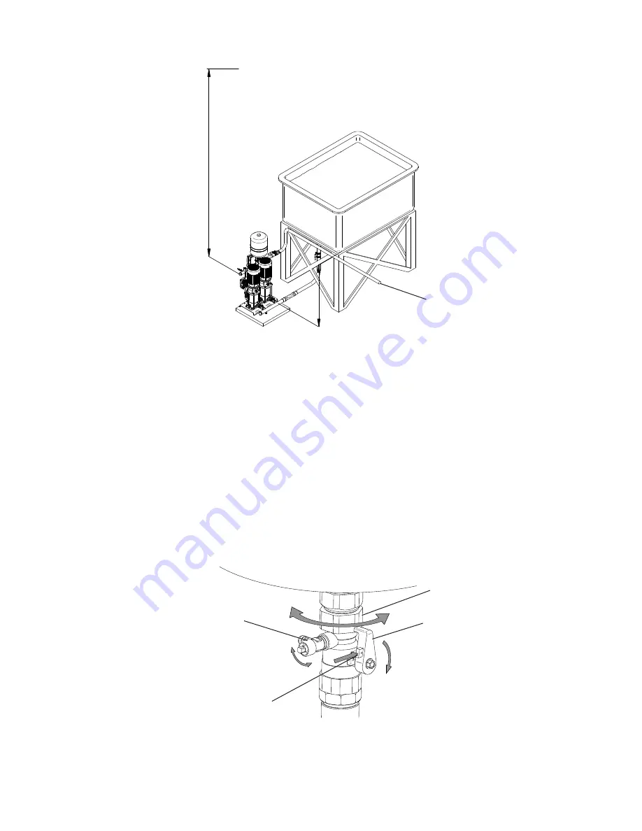
3.12 The suction and discharge caps can be installed on either end of the manifold to
facilitate ease of installation, please ensure these are water tight before switching
the unit on (see Fig. 1).
3.13
Pressure vessel:
The pressure vessel is supplied loose, this must be fitted to
the connection on the discharge pipework. The connection is sealed with two
‘O’-rings within the end of the connection, ensure the ‘O’-rings are not damaged
during assembly. To fit the vessel tighten the running nut and open the isolation
valve.
3.14
DO NOT
install the booster set where the control panel can be exposed to direct
sunlight or near sources of heat.
3.15 Non-return valves
must not
be fitted to suction or delivery as this may cause
incorrect operation and damage to the unit.
3 INSTALLATION
Fig. 3
Outlet to the
system
Static inlet pr
essur
e
Min.
1
m
Max.
10
m
Static outlet pr
essur
e
Max.
13
m
Fig. 4
Running nut
Turn lever to isolate
pressure vessel
Drain valve
Press button


