


- 10 -
Cont ...
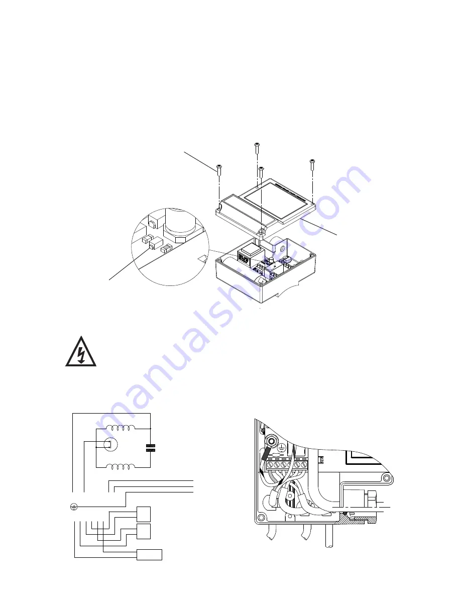
To view the light the following procedure must be followed:-
•
Isolate the mains electrical power supply from the pump.
•
Remove the four screws (item 23) retaining the terminal box lid.
•
Lift the terminal box lid off.
•
IMPORTANT
– Ensure there is no contact with any of the internal parts of the terminal box.
•
Briefly reconnect the mains power supply to the pump – the indicator light should illuminate if
the pump has been correctly wired.
•
Isolate the mains electrical power supply from the pump.
•
Re fit the terminal box lid ensuring no cables are trapped.
•
Re fit the four terminal box lid retaining screws, tighten to 0.8 Nm.
•
DISASSEMBLY
•
Isolate electrical supply before fitting replacement part.
•
Replacing the PCB should only be carried out by a competent person.
•
The supply cord and internal wiring within the terminal box are routed
and secured to ensure compliance with the electrical standard
EN 60335-1. It is essential that prior to any disturbance of this internal
wiring, all cable routing and securing details are carefully noted to
ensure reassembly to the same factory pattern is always maintained.
Indication light
Terminal box lid
23
Fig. 15 Wiring removed for clarity
N
S1
S2
S2
S3 S3
MAIN WINDING
THERMOTRIP
CAPACITOR
START WINDING
FLOWSWITCH
REED (S3)
BLUE
BROWN
BL
AC
K
RE
D
GREEN/
YELLOW
BLUE
BROWN
L
M
N
N
S2 S3 S3 S2
L
E
N
FLOWSWITCH
REED (S2)
S1
S1
PRESSURE
SWITCH (S1)
230 VAC/1PH/50Hz
SUPPLY
S1
Fig. 16 Twin


