background image

7110-120-700 Rev-AB

EN

www.stryker.com

9

•  The use of abrasive disinfectants, such as 

Clorox bleach, can lead to build-up on the 
contacts which may affect the functionality of 
the charger module.  

•  DO NOT allow liquid to collect in the charger 

modules or on top of the battery charger.

•  DO NOT allow liquid to enter the cooling vents 

on the back of the battery charger.

•  DO NOT spray or wipe liquid directly on the 

contacts of the charger modules.

•  DO NOT sterilize the battery charger or 

charger modules.

1.  Disconnect the power cord from the facility 

power receptacle and the battery charger.

2.  Disconnect the Ethernet cable, if used, from 

the isolated diagnostics port.

3.  Gently wipe the external surfaces of the 

battery charger and power cord with a soft, 
lint-free cloth moistened with a prepared 
cleaning solution or non-abrasive, hospital 
disinfectant and water. 

4.  Immediately dry the battery charger with 

a soft, lint-free cloth or compressed air, 
< 140 kPa [< 20 psi]. 

5.  Inspect the battery charger and power cord 

for damage. See the 

Inspection and Testing


section for inspection criteria.  

To Clean the Battery Pack

For battery pack processing instructions, see the 
care instructions manual supplied with the battery 
pack and/or a compatible handpiece.

Inspection and Testing

WARNINGS:

•  Only individuals trained and experienced in 

the maintenance of reusable medical devices 
should inspect and test this equipment.

•  Before attempting any inspection and testing, 

ALWAYS disconnect the power cord from the 
battery charger to reduce the risk of electric 
shock. 

•  Perform recommended inspection and testing 

as indicated in these instructions. 

•  DO NOT use any equipment if damage is 

apparent.

•  DO NOT use any system component if the 

inspection criteria are not met.

•  DO NOT disassemble or service this 

equipment. Failure to comply may result in 
electric shock or fire.

NOTES: 

•  If the equipment fails to meet the inspection 

and testing criteria, contact your Stryker sales 
representative or call Stryker customer service. 
Outside the US, contact your nearest Stryker 
subsidiary. 

•  Maintenance documentation for this equipment 

is available upon request to Stryker-authorized 
service personnel only.

INTERVAL

ACTIVITY

CRITERIA

Upon initial 
receipt and 
before each 
use

Inspect the 
equipment

No damage or 
signs of wear

No loose 
or missing 
components

No cuts in the 
power cord

No bent pins or 
contacts

No cracks in the 
housing

Storage and Handling

CAUTION: 

ALWAYS store the equipment within 

the specified environmental condition values 
throughout its useful life. See the 

Specifications


section.
To ensure longevity, performance, and safety, 
use of the original packaging materials is 
recommended when storing or transporting this 
equipment. 

Summary of Contents for 7110-190-000

Page 1: ...2020 08 7110 120 700 Rev AB www stryker com Instructions For Use ENGLISH EN Universal Battery Charger REF REF 7110 120 000 Stryker F1 Universal Battery Charger REF REF 7110 190 000 ...

Page 2: ...r with a damaged power cord or plug Introduction This instructions for use manual contains information intended to ensure the safe effective and compliant use of your product This manual is intended for in service trainers physicians nurses surgical technologists and biomedical equipment technicians Keep and consult this reference manual during the life of the product The following conventions are...

Page 3: ...es WARNINGS Use only Stryker approved equipment unless otherwise specified DO NOT modify any equipment without the authorization of the manufacturer Use only Stryker approved electronic components and accessories Failure to comply may result in degraded performance increased electromagnetic emissions or decreased electromagnetic immunity of the system DO NOT use any battery charger accessory that ...

Page 4: ...and battery packs E Input Buttons Allow the user to interact with the battery charger The information screen displays appropriate input button labels during the battery pack charging sequence F Power Cord Receptacle Accepts the power cord G Power Cord Connects the battery charger to a hospital grade facility power receptacle H Isolated Diagnostics Port An Ethernet receptacle used to export device ...

Page 5: ...e battery charger is either charging or discharging the battery pack AMBER Slow Blinking The battery pack is at or near the end of its useful life AMBER Fast Blinking The battery charger or charger module failed diagnostic testing Definitions The symbols located on the equipment and or labeling are defined in this section or in the Symbol Definition Chart See the Symbol Definition Chart supplied w...

Page 6: ...ll begin A diagnostic test will be performed to ensure the battery charger and each installed charger module is operational The battery charger software and hardware revision numbers will appear figures 2 and 3 The charger module revision number will appear for each installed charger module figure 4 NOTE If an ERROR message appears during the power up sequence note the error code that appears in t...

Page 7: ...ule Orientation 1 Install a clean dry battery pack into a compatible charger module with a NO BATTERY message screen figure 7 The information screen will momentarily display the battery pack part number figure 8 and the charging sequence will begin During the charging sequence a CHARGING message will appear and the number of illuminated state of health bars will increase from left to right figure ...

Page 8: ...n NOTES Specific types of battery packs allow you to access information about battery pack exposure to over temperature conditions The information screen will return to its origin after displaying an over temperature message screen for five seconds 1 From the READY CHARGING or REPLACE message screen press the MORE button to access the of OVER TEMP message screen The counter will display the number...

Page 9: ...on and Testing WARNINGS Only individuals trained and experienced in the maintenance of reusable medical devices should inspect and test this equipment Before attempting any inspection and testing ALWAYS disconnect the power cord from the battery charger to reduce the risk of electric shock Perform recommended inspection and testing as indicated in these instructions DO NOT use any equipment if dam...

Page 10: ...ard SJ T 11364 To comply with China RoHS Standard SJ T 11364 this device has been marked with the environmentally friendly use period EFUP number measured in years The device contains at least one of the listed hazardous substances above threshold China RoHS Disclosure Report REF 7110 120 000 REF 7110 190 000 Part Name Hazardous Substances Lead Pb Mercury Hg Cadmium Cd Hexavalent Chromium Cr VI Po...

Page 11: ...wer to battery charger Reseat the cord connections on back of the battery charger and the facility power receptacle Battery charger is damaged Return the battery charger for repair NO MODULE appears in the message area of the information screen Charger module Charger module is not properly connected Reseat the charger module connectors See the instructions for use supplied with the charger module ...

Page 12: ...en NO BATTERY and CHARGING Battery pack Battery pack has low voltage Leave the battery pack on the charger module for a minimum of five minutes If the problem persists check other causes Battery pack is dead Replace the battery pack REPLACE appears in the message area of the information screen Battery pack Battery pack is wet Dry and reinstall the battery pack Battery pack has exceeded its operati...

Page 13: ...he charge cycle Wait until the charge cycle is complete Information screen does not display charge cycle count information Battery pack Battery pack is not a Stryker approved battery pack Use Stryker battery packs only Battery pack Charger module Battery pack REF 4112 000 000 is not a design integrated component No action required Amber indicator light flashes continuously Battery pack charger mod...

Page 14: ... battery packs only Charger module Charger module contact is corroded Clean the charger module contact Charger module contact is damaged Replace the charger module Battery charger Battery charger contact is corroded Clean the battery charger contact Battery charger contact is damaged Return the battery charger for repair ERROR code 007 appears in the counter area of the information screen for a sh...

Page 15: ...ion Electrical Input 100 230 V 50 60 Hz 2 2 1 A Output 22 V Ingress Protection IPX0 Equipment Type Class I Ground Type Protective Earth Ground Means of Isolation from Supply Mains Disconnect the power cord from the battery charger power cord receptacle Network Requirements Purpose of the Connection Device Usage Data Required Network Characteristics Standard TCP IP over Ethernet IEEE 802 3 10 100 M...

Page 16: ...shielded Length 3 0 m 2 5 m NOTE The 2 5 m cord is not for use in Canada or the US Dielectric Withstand 1500 VAC for 60 seconds between line and protective earth and between neutral and protective earth Certification All applicable in country medical electrical requirements Power Cord Requirements specific The Canadian and US power supply cord shall have a tag or label in English and French indica...

Page 17: ...7110 120 700 Rev AB EN www stryker com 17 Environmental Conditions Operation Storage and Transportation Temperature Humidity Atmospheric Pressure ...

Page 18: ...r F1 Universal Battery Charger REF 7110 190 000 use RF energy only for their internal function Therefore their RF emissions are very low and are not likely to cause any interference in nearby electronic equipment RF emissions Class A NOTE The emissions characteristics of this equipment make it suitable for use in industrial areas and hospitals CISPR 11 class A If it is used in a residential enviro...

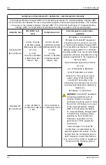
Page 19: ... s 0 5 1 2 kV line s to earth Mains power quality should be that of a typical commercial or hospital environment Voltage dips short interruptions and voltage variations on power supply input lines IEC 61000 4 11 5 UT 95 dip in UT for 0 5 cycle 0 UT 100 dip in UT for 0 5 cycle at 0 45 90 135 180 225 270 and 315 0 UT 100 dip in UT for 1 cycle at 0 40 UT 60 dip in UT for 5 cycles 70 UT 30 dip in UT f...

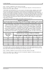
Page 20: ...ttery Charger REF 7110 190 000 including cables than the recommended separation distance calculated from the equation applicable to the frequency of the transmitter Recommended separation distance d 1 2 P d 1 2 P 80 MHz to 800 MHz d 2 3 P 800 MHz to 2 5 GHz Where P is the maximum output power rating of the transmitter in watts W according to the transmitter manufacturer and d is the recommended se...

Page 21: ...the Universal Battery Charger REF 7110 120 000 and Stryker F1 Universal Battery Charger REF 7110 190 000 The Universal Battery Charger REF 7110 120 000 and Stryker F1 Universal Battery Charger REF 7110 190 000 are intended for use in the electromagnetic environment in which radiated RF disturbances are controlled The customer or the user of the Universal Battery Charger REF 7110 120 000 and Stryke...

Page 22: ......

Page 23: ......

Page 24: ...stryker com Stryker Instruments 1941 Stryker Way Portage Michigan USA 49002 1 269 323 7700 1 800 253 3210 ES DE FR IT NL 7110 120 710 JA ZH KO 7110 120 720 SV DA FI PT NO 7110 120 730 PL EL 7110 120 750 TR 7210 120 762 RU 7210 120 770 ...

Reviews: