


User ManUal
w w w. s t r a n d l i g H t i n g .co M
Vision.net Hardware
18
8
VIsIOn.neT
TOUCHsCreens
02.1707.0020
1
VISION.NET TOUCHSCREEN
QUICK START GUIDE
OVERVIEW
This document provides installation and operation instructions for the following product(s):
INSTALLATION AND SET UP
POWER REQUIREMENTS
Vision.net Touchscreen operates on 24VDC. It is powered through the Touchscreen control PCB (pre-installed on
the back of the touchscreen) via an external AC to DC power supply. It may alternatively be powered from a PoE+
(IEEE802.3at) compliant supply, using the RJ45 ethernet connector.
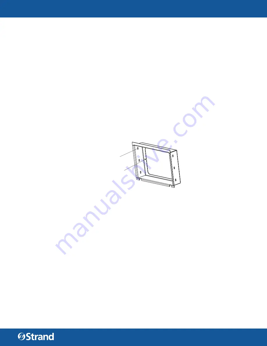
MOUNTING / INSTALLATION
To mount the touchscreen:
Step 1.
For surface and fl ush mount options, install the back box in the required location.
Step 2.
Fix the bezel in place, using the two supplied screws in position A (the screws are over length to
accomodate varying thicknesses when fl ush mounting)
Step 3.
Connect the required cables to the screen connectors (see “Connecting Power” on page 3).
Step 4.
Mount the touchscreen by inserting the screen assembly into the bezel. Spring tabs on the touch-
screen click into slots “B” on the bezel, securing the touchscreen.
A (x2)
B (x6)
PRODUCT NAME
ORDER CODE
10.1 inch Touchscreen assembly, compatible with Desktop Stand, 19”
rack plate,
ush or surface mount box accessories. For custom
applications use with 10.1707.0501.
95610
Desktop stand portable
95622
4U 19” rack plate with mounting bezel
95623
Flush mounting box with mounting bezel
66824
Surface mounting box with mounting bezel
66825
Locking cover
66830
ACCESSORIES
Mounting bezel (optional for custom applications)
10.1707.0501
Vision.net touchscreen processor electronics box
(for use with external monitor)
95631
COMPATIBLE MONITORS
15” monitor
Required 7U rack plate
ELO E3317992
10.1707.0113
24” monitor
DELL P2418HT
PLANAR PCT2435
02.1707.0020
1
VISION.NET TOUCHSCREEN
QUICK START GUIDE
OVERVIEW
This document provides installation and operation instructions for the following product(s):
INSTALLATION AND SET UP
POWER REQUIREMENTS
Vision.net Touchscreen operates on 24VDC. It is powered through the Touchscreen control PCB (pre-installed on
the back of the touchscreen) via an external AC to DC power supply. It may alternatively be powered from a PoE+
(IEEE802.3at) compliant supply, using the RJ45 ethernet connector.
MOUNTING / INSTALLATION
To mount the touchscreen:
Step 1.
For surface and fl ush mount options, install the back box in the required location.
Step 2.
Fix the bezel in place, using the two supplied screws in position A (the screws are over length to
accomodate varying thicknesses when fl ush mounting)
Step 3.
Connect the required cables to the screen connectors (see “Connecting Power” on page 3).
Step 4.
Mount the touchscreen by inserting the screen assembly into the bezel. Spring tabs on the touch-
screen click into slots “B” on the bezel, securing the touchscreen.
A (x2)
B (x6)
PRODUCT NAME
ORDER CODE
10.1 inch Touchscreen assembly, compatible with Desktop Stand, 19”
rack plate,
ush or surface mount box accessories. For custom
applications use with 10.1707.0501.
95610
Desktop stand portable
95622
4U 19” rack plate with mounting bezel
95623
Flush mounting box with mounting bezel
66824
Surface mounting box with mounting bezel
66825
Locking cover
66830
ACCESSORIES
Mounting bezel (optional for custom applications)
10.1707.0501
Vision.net touchscreen processor electronics box
(for use with external monitor)
95631
COMPATIBLE MONITORS
15” monitor
Required 7U rack plate
ELO E3317992
10.1707.0113
24” monitor
DELL P2418HT
PLANAR PCT2435


