


User ManUal
w w w. s t r a n d l i g H t i n g .co M
Vision.net Hardware
16
7
VIsIOn.neT sensOrs
OCCUPANCY SENSORS
This section provides installation and programming instructions for the following Vision.net Products:
• 63059CM - Vision.net Ceiling Occupancy Sensor
• 63059HB - Vision.net High Bay Ceiling Occupancy Sensor
IMPORTANT INFORMATION. PLEASE READ!
This unit is intended for installation in accordance with the National Electric Code® and local regulations. It is
also intended for permanent installation in indoor applications only. Before any electrical work is performed,
disconnect power at the circuit breaker or remove the fuse to avoid shock or damage to the control. It is recom-
mended that a qualified electrician perform this installation.
DesCrIPTIOn
The Vision.net Low-Voltage Ceiling Occupancy Sensor is a
multiple technology, occupancy-sensing low-voltage device
that is designed for use with a Vision.net architectural
control system. Each sensor may be programmed to act as
a Vision.net button (like Preset, Preset/Off, Toggle, Smart,
Console) providing the ability to execute any Vision.net
command across the architectural control network.
InsTallaTIOn
The Ceiling Occupancy Sensor may be mounted in a junction box or directly to the ceiling depending on local
code. The unit must have an unobstructed view of the area to be monitored. If the unit is subject to “false trig-
gering” from activity beyond the desired area of coverage, a portion of the lens may be masked to achieve the
desired response. Simply install the Field of View Customizing Template (provided with unit).
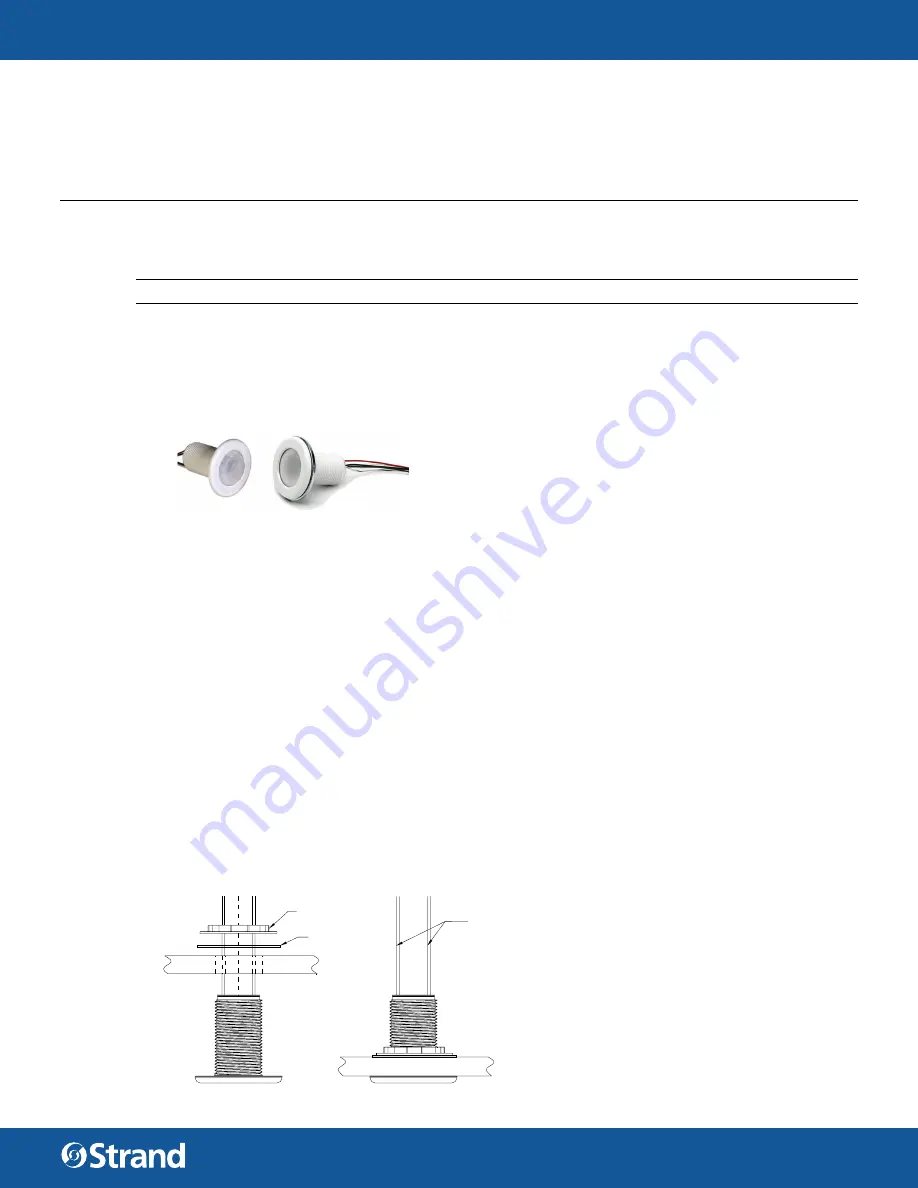
To install ceiling occupancy sensors:
Step 1.
Check for any obstructions located behind the desired mounting location.
Step 2. Drill 1-1/2 inch hole in the desired mounting location.
Step 3. Place Ceiling Occupancy Sensor through the hole and secure with supplied washer and locknut.
Step 4. The lens may be removed to install the Field of View Customizing Template. Simply rotate the lens
cover slightly counter-clockwise and remove.
Step 5. Trim the template for the desired effect and install on interior of the lens. (Carefully placement of the
template is necessary to ensure proper function.)
Step 6. Replace lens cover and verify that the unit is securely mounted.
Vision.net Ceiling Occupancy Sensors
(63059CM, 63059HB)
RETAINING NUT
WASHER
LOW VOLTAGE
WIRE


