


USER MANUAL
CONTACT LIGHTING CONTROL PANEL
WWW. ST R A N D L I G H T I N G .CO M
9
OVERVIEW
The Contact Lighting Control System can be confi gured directly at the Rack Control Module (RCM) processor
using the built-in LCD Menu or via Vision.Net Designer software. For more information on Vision.Net Designer,
visit the Strand web site at
www.strandlighting.com.
MENU OPERATION
The RCM LCD Menu provides local control for accessing all system status information and for making a limited
amount of confi guration changes to that particular RCM processor. (If there are multiple RCMs in the system,
changes would need to be made at each RCM.)
Upon power up, the LCD Menu will display the Strand Lighting logo followed by the current RCM software ver-
sion and RCM name. After briefl y displaying this information, the MAIN MENU will appear.
NOTE:
To return to the power up screen after boot up, press the [Escape] button.
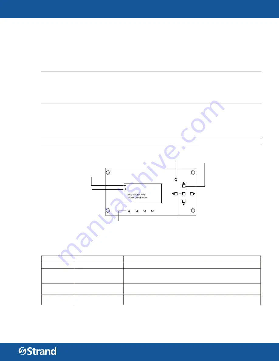
FIGURE 6.
LCD MENU
LED Status Indications:
LED
CONDITION
MEANING
POWER
Flashing Green
Indicates power is active to the Rack Control Module (RCM) processor.
FAULT
Flashing or Steady Red
Indicates an error condition in the cabinet. If illuminated, remove power
to the panel, wait 15 seconds, and re-energize panel. If error condition
persists, please contact Strand Lighting Technical Support.
Vision.Net
Illuminating Yellow
Indicates presence of Vision.Net control signal. (Not constant. Only
fl
ashes when Vision.Net is sending data.)
DMX
Illuminating Yellow
Indicates presence of USITT DMX512 control signal. Constant on when
DMX512 signal is present.
Escape Button -
Right/Left/Up/Down Buttons (4) -
Backs up one menu level.
Navigates menu system.
Arrow Indicator -
Indicates menu can be
scrolled to view more
choices.
Accesses details, activates a field, or
enters a setting, depending on current menu
and cursor location.
MAIN MENU:
System Status
Relay Status
Walk Around Programming
POWER
FAULT VISION.NET DMX
ESCAPE
Status LEDs
Menu
Enter Button -
4
CONFIGURATION USING
RCM LCD MENU


