background image

35

GB

Combustion check at full load

Start 

the 

boiler 

in 

controller 

stop  mode  and  go  to  50%  load. 
Now  the  boiler  operates  at  50% 
load.  Allow  the  boiler  to  stabili-
ze  the  combustion  for  3  minutes.
Then  increase  the  boiler  load  step
by  step  up  to  100%.  Check  the  gas
pressure on the inlet of the gas valve

ZKLOH LQFUHDVLQJ WKH ERLOHU ORDG WKH

gas pressure should never go below
the  minimum  required  value 

ĺ

  see

technical  data

.  When  an  (optional)

minimum  gas  pressure  switch  is
connected,  this  must  be  set  to 
75%  of  the  required  gas  pressure.

Check  the  combustion  settings  via 
the  test  point  in  the  chimney  con-

QHFWLRQ,IQHFHVVDU\FRUUHFWWKH

settings  with  the  small  adjustment 
screw at the top of the gas valve (2).
Combustion check at minimum load.
Switch    the    boiler  to  minimum  load 
(0%).

Check  the  combustion  settings 
the  same  way  as  described  for  full 

ORDG ,I QHFHVVDU\ FRUUHFW WKH VHW

-

tings  with  the  large  adjustment 
screw at the top of the gas valve (3).

Combustion check at 50% load

An  additional  reference  check  of
combustion  values  at  50%  load  is
recommended in order to check if the 
gas valve is set in such way, that the 
modulating behaviour is normal. The 
CO

2

 value should be in between the 

settings  of  full  load  and  minumum 
load.  CO  value  should  be  equal  to 
full  load  and  minimum  load  values.

Make  sure  that  the  boiler  is  set  to
automatic  operation  and  control-
ler  stop  mode  is  disabled  after 

WKH FRPEXVWLRQ WHVW LV ¿QLVKHG

2

3

Commissioning

Combustion check
Combustion settings

1

+

-

-

+

SW 2

SW 3

Combustion settings max. load 

for natural gas G20 / G25

R40 45-155

CO

max

%

± 0.2

Combustion settings min. load 

for natural gas G20 / G25

R40 45-155

CO

min

%

± 0.2

Summary of Contents for ECONOFLAME R40

Page 1: ...tallation Operation Maintenance Manual STOKVIS ENERGY SYSTEMS 96R Walton Road East Molesey Surrey KT8 0DL Tel 020 8783 3050 0870 7707747 Fax 020 8783 3051 0870 7707767 E Mail info stokvisboilers com Website www stokvisboilers com 420010685900 09 2015 ErP ...

Page 2: ...ation 15 Boiler transport 15 Removing the casing 15 Warnings before installation 16 Boiler installation 17 Connecting the boiler 17 Air Flue gas system 18 Air Flue pipe data 19 Air Flue gas system dimensioning 21 Accessories 22 Installation Instructions coaxial 23 Installation Instructions twin pipe 24 Installation of vertical flue terminals 25 Installation of horizontal flue terminals 26 Electric...

Page 3: ...up procedure 34 Combustion check 35 Combustion settings 35 Check water flow 36 Check safety devices 37 Boiler shut down 37 Commissioning Protocol 38 Controls 39 Display Programming 40 Overview of main functions 41 Maintenance 42 Checklist 42 Cleaning 43 Physical and chemical check 44 Maintenance Protocol 45 Lockouts 46 Sensor Values 48 Declaration of Conformity 49 Note 50 ...

Page 4: ...2 B3 B5 with a nominal heat input not exceeding 1000 kW EN 656 1999 DV UHG FHQWUDO heating boilers Type B boilers of nominal heat input exceeding 70 kW but not exceeding 300 kW EN 483 1999 DV UHG FHQWUDO heating boilers Type C boilers of nominal heat input not exceeding 70 kW EN 15420 2010 DV UHG FHQWUDO heating boilers Type C boilers of nominal heat input exceeding 70 kW but not exceeding 1000 kW...

Page 5: ... WKH FDVH SOHDVH contact your supplier Keep all packaging material clips plastic bags polystyrene foam etc out of reach of children as it may pre sent a potential hazard Before any maintenance or repair work is performed on the boiler make sure you have disconnected it from the electricity supply by switching the external bipolar switch to the OFF position All repairs should only be performed usin...

Page 6: ...cal data 10 Factory settings 11 Maximum water pressure 12 Boiler type 13 12 FODVV I FLHQF 14 QSXW UDWLQJ QRPLQDO KHDWLQJ 15 Power output heating 16 Gases which may be used 17 Ambient operating temperature Max central heating temperature 26 05 2015 S N 0000000KE000000000000 00 100 min η η MAX MIN Q Hi P P 60 80C 30 50C gas mbar gas mbar gas mbar 1 2 3 4 5 6 7 9 10 11 12 13 14 15 16 17 General regul...

Page 7: ...H ÀRZ FRQQHFWLRQ 7KH FURVV ÀRZ ZRUNLQJ SULQFLSOH ZD WHU XS ÀXH JDV GRZQ HQVXUHV WKH PRVW HI FLHQW FRPEXVWLRQ UHVXOWV The LMS14 control unit can control WKH ERLOHU RSHUDWLRQ EDVHG RQ boiler control standalone opera tion weather compensated operation with optional outdoor sensor ZLWK 9 H WHUQDO LQÀXHQFH temperature or capacity from a building management system Layout of boiler The boiler consists of...

Page 8: ...0 100 R40 120 R40 150 Nominal heat output at 80 60ºC max min Nominal heat output at 75 60ºC max min Nominal heat output at 40 30ºC max min Nominal heat input Hi max min Efficiency at 80 60ºC Efficiency at 40 30ºC Annual efficiency NNG 75 60ºC Annual efficiency NNG 40 30ºC Heat Loss Pstby Max condensate flow Gas consumption G20 max min 10 9 kWh m3 Gas consumption G25 max min 8 34 kWh m3 Gas consump...

Page 9: ...ng energy effi ciency Ks 92 92 92 92 92 92 At rated heat output and high temperatu re regime 2 K4 87 7 87 7 87 7 87 9 87 9 87 9 At 30 of rated heat output and low temperature regime 1 K1 96 5 96 5 96 5 96 5 96 5 96 5 Auxiliary electricity consumption At full load elmax kW 0 100 0 100 0 214 0 214 0 214 0 221 At rated heat output and high tempera ture regime elmin kW 0 025 0 025 0 038 0 038 0 038 0 ...

Page 10: ...92 Sound power level indoors outdoors LWA dB 62 62 Important The installation consisting of the boiler and all accessories including temperature control together define the seasonal heating energy efficiency Ks for the various models as listed in the below table R40 45 50 65 Class VI with use of components R40 Ambient temperature sensor QAA 75 option External temperature sensor QAC 34 Temperature ...

Page 11: ...m R 3 4 R 3 4 R 1 R 1 R 1 F mm 100 100 100 100 130 A mm 100 100 100 100 130 B mm 490 490 590 590 590 B1 mm 140 140 140 140 190 B2 mm 245 245 295 295 295 D mm 500 500 600 600 600 H mm 950 950 950 W1 mm R1 1 4 R1 1 4 R1 1 2 R1 1 2 R1 1 2 W2 mm R1 1 4 R1 1 4 R1 1 2 R1 1 2 R1 1 2 G mm R3 4 R3 4 R1 R1 R1 F DN mm 100 100 100 100 130 A DN mm 100 100 100 100 130 DN 100 Øint 101 0 7 mm DN 130 Øint 131 0 7 ...

Page 12: ...as valve and or room fan con trol in combination with an alarm signal For each boiler a maxi mum of 3 AGU2 550 modules 2x heating zone 1x ext gas valve room fan in combination with alarm can be integrated in the boiler t Additional RVS63 heating zone controller when controlling more than 2 zones incl wall hung box all necessary sensors and so ckets and connection material for bus communication The...

Page 13: ...le to transport all models through a nor mal door in one piece The Boiler can be transported with a crane but it has to be ensured that WKH ERLOHU LV SDFNHG DQG HG RQ D pallet The straps must be connected to the pallet Removing the casing Remove the casing before installing the boiler in order to avoid damage to the casing parts Removing the casing is done as shown on the pictures 1 2 3 Installati...

Page 14: ...already a con QHFWLRQ WR H LVWLQJ ÀXH H KDXVWV check that these exhausts have been perfectly cleaned and are without residues because any disconnection could obstruct the passage of fumes and create po tentially dangerous situations t Make sure that where unsuitable ÀXH H KDXVWV DUH DWWDFKHG WKH have been ducted t Q DUHDV ZLWK SDUWLFXODUO KDUG water limescale may build up on the components inside ...

Page 15: ... be mounted directly to the return connection 2 of the boiler before connecting to the system Condensate connection 5 IWHU OOLQJ ZLWK ZDWHU WKH V SKRQ included in delivery should be instal led to the connection 5 at the bottom of the boiler Connect the hose to the draining system in the boiler room The connection to the draining system should always be done with an open FRQQHFWLRQ LQ RUGHU WR DYRL...

Page 16: ...areful when handling the seals LQ RUGHU WR DYRLG ÀXH JDV OHDNLQJ LQWR the air circuit RQQHFW WKH ÀXH JDV V VWHP WR WKH ÀXH JDV FRQQHFWLRQ RI WKH ERLOHU XVH ÀXHJDV V VWHPV ZLWK VHDPOHVV connections only W V QRW QHFHVVDU WR PDNH D VHSDUD WH FRQGHQVDWH GUDLQ IRU WKH ÀXH JDV system as the condensate will be drained via the syphon of the boiler The horizontal kit must be tilted with a downward slope of...

Page 17: ...Location class Concentric pipe Only outside buildings Single pipe Only inside buildings Fire rating class E Outer wall class Concentric pipe only L0 Distance to combustible materials Concentric pipe 00 mm Single pipe 30 mm 1 0 0 5 1 0 0 5 Installation Air Flue gas system Flue Gas data Boiler type Nominal heat output Nominal heat input Flue gas connection DN CO ഺ Level Flue gas temperature Flue gas...

Page 18: ...OO EH OHVV WKDQ FP IRU ERLOHUV with a heat input below 70 kW A square of 100 cm and distance between the planes of the two RUH FHV VKDOO EH OHVV WKDQ FP ZLWK D KHDW LQSXW DERYH N C43 QGLYLGXDO RU VKDUHG ÀXH JDV H KDXVW DQG DLU VXFWLRQ WKURXJK ÀXH ducting built into the building C53 Flue gas exhaust leading outside and air suction duct through external wall not in the same range of pressure C63 Air...

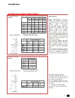
Page 19: ...Q EDVH 7RWDO FRQQHFWLRQ OHQJWK LQ ERLOHU URRP P EHQG RLOHU W SH 7 7 7 VER DOFXODWLRQ EDVH 7RWDO FRQQHFWLRQ OHQJWK LQ ERLOHU URRP P EHQG Maximum permissible height h of flue gas system in m RLOHU W SH TH L 65 6 61 7 7 7 TH L 145 14 27 34 36 TH L 50 6 61 DOFXODWLRQ EDVH URRI RU ZDOO WHUPLQDO 7KH 7 6 21 ERLOHU PRGHOV DOFXODWLRQ EDVH 7RWDO FRQQHFWLRQ OHQJWK LQ ERLOHU URRP P EHQG Maximum permissible he...

Page 20: ...cessories catalogue Supplementary resistance must be borne in mind during the sizing process mentioned above For the calculation method equiva lent length values and installation H DPSOHV SOHDVH UHIHU WR WKH JDV ÀXH accessories catalogue Installation Air Flue gas system Accessories Flue adapter concentric RQFHQWULF ÀXH V VWHPV FDQ EH XVHG on the R40 45 120 by using a paral lel to concentric adapte...

Page 21: ...7 8VH RQO ZDWHU DV OXEULFDQW Pipes bends When using bends the maximum SHUPLVVLEOH OHQJWK RI ÀXH JDV V VWHP can be deducted from the table on page 21 3LSH H WHQVLRQV PXVW EH HG WR WKH wall using support clips Use one clamp for each extension directly be side the sleeve Fit another clamp to the extension after each 90 bend Important QVWDOO RQO RXWVLGH EXLOGLQJV RQ XQÀD mable wall Cleaning Outside ca...

Page 22: ...bottom of the joint 127 RQ W XVH VRDS RLO OXEULFDQW Use only water as lubricant Before pipe exensions When using bends the maximum SHUPLVVLEOH OHQJWK RI ÀXH JDV V VWHP can be deducted from the table on pag 21 Important QVWDOO RQO LQVLGH EXLOGLQJV RQ XQÀD mable wall Cleaning Outside can be cleaned with a wet towel or with some detergent L 500 mm L 250 mm L 2 5 0 m m L 250 mm L 250 mm o r o r 3 QVWD...

Page 23: ... LQWR D YHUWL cal position using an air level I GHVLUHG FRYHU SODWHV WR EH VXS SOLHG VHSDUDWHO FDQ EH WWHG D Fix the supplied wall clamp round WKH ÀXH WHUPLQDO DQG W LW WR WKH roof construction without tighten the clamp yet Concentric HWHUPLQH WKH OHQJWK RI WKH ÀXH SLSHV and install these with the clamps in accordance with the installation in structions in the previous pages Twin tube Fit the gask...

Page 24: ...s WWHQWLRQ The length is correct if the outer wall SODWH RU URVHWWH DUH ÀXVK ZLWK WKH RW side wall Part list RUL RQWDO ÀXH WHUPLQDO 2 Wall plate or rosette 3 Concentric bend 4 Locking bend optional 5 Flue pipe 6 Air inlet pipe 7 Twin pipe connection QVHUW WKH ÀXH WHUPLQDO LQWR WKH GULOOHG KROH 7KH DLU VXSSO SLSH IRU WKH ÀXH terminal must either be installed le vel or tilted slightly downwards to t...

Page 25: ...m within the boiler room This switch can be used to switch off the power supply for maintenance purposes All cables should be lead throu gh the cable glants 9 at the bottom of the boiler into the electro panel 10 Outside sensor mounting I DQ RXWVLGH VHQVRU DFFHVVRU LV connected to the boiler the sensor should be positioned as shown on the drawing Connect all wires to the terminals according to the...

Page 26: ...28 Op 01 Op 02 Op 03 Op 04 P F 01 F 02 Dp 01 Op 05 PCB Installation Wiring diagram Boiler ...

Page 27: ...ipln Components X2 1 Gas Valve Op 01 Load feedback optional X2 3 Ignition transformer Op 02 Alarm optional X2 3 1 Ionization electrode Op 03 Zone 2 optional X3 Ignition electrode Op 04 Zone 1 optional BX3 Flue gas temp sensor Op 05 Unit QAA75 optional B9 1 Resistor PCB PCB LMS14 Card H3 Min water pressure sensor F 01 Fan Type 50 B7 Return temp sensor F 02 Fan Other types H7 Thermostat Dp 01 Displa...

Page 28: ...30 P Op 01 Op 02 Op 03 Op 04 Installation Wiring diagram Accessories ...

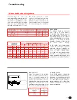
Page 29: ...ation between the water TXDOLW DQG WKH PD LPXP ZDWHU OOLQJ volumeduringthelifetimeoftheboiler Water pressure Open the valves to the system Check the water pressure in the sy VWHP I WKH ZDWHU SUHVVXUH LV WRR low see table below increase the pressure up to at least the minimum required water pressure in the table Filling can eventually be done via the RSWLRQDO OO DQG GUDLQ YDOYH RQ the return connec...

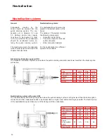
Page 30: ...sate for each boiler type can be found in the chapter Technical data Neutralisation systems The neutralisation systems can be placed in the bottom section of the boiler The delivery of the system contains WKH IROORZLQJ FRPSRQHQWV t UDQXODWH IRU UVW OOLQJ t Connection hoses for inlet and outlet connection t Boiler connection adapter For the neutralisation two different V VWHPV DUH DYDLODEOH Standar...

Page 31: ...to know for which gas type the boiler should be commissioned Condensate connection Remove the syphon 2 from the condensate connection Fill it with water and place it back in the origi nal position Make sure the syphon LV OOHG EHIRUH VWDUWLQJ WKH ERLOHU LQ RUGHU WR SUHYHQW ÀXH JDVHV GLVFKDUJLQJ WKURXJK WKH FRQGHQVDWH FRQQHFWLRQ Flue and air intake connections KHFN ZKHWKHU WKH ÀXH DQG DLU LQWD ke sy...

Page 32: ...ney sweeper mode QIR PRGH H Reset button 2SHUDWLRQ PRGH KHDWLQJ RQH V L Display M Operation mode DHW x x x x x x x x x M A H B C D E F I L G Initial procedures To guarantee safety and the correct operation of the appliance the boiler must be prepared for operation by a TXDOL HG WHFKQLFLDQ ZKR SRVVHVVHV the skills which are required by law Electricity supply t Check that the voltage and fre quency ...

Page 33: ...heck at minimum load Switch the boiler to minimum load 0 Check the combustion settings the same way as described for full ORDG I QHFHVVDU FRUUHFW WKH VHW tings with the large adjustment screw at the top of the gas valve 3 Combustion check at 50 load An additional reference check of combustion values at 50 load is recommended in order to check if the gas valve is set in such way that the modulating...

Page 34: ... qactual ǻ7nominal ǻ7measured qnominal m3 h ǻS PHDVXUHPHQW Check the pressure difference over WKH ERLOHU ǻS ÀRZ UHWXUQ ZKHQ WKH boiler pump is running burner on LV QRW UHTXLUHG 7KH QRPLQDO ǻS IRU each boiler type can be found in the WDEOH EHORZ DFWXDO ǻS PXVW EH ZLWKLQ ǻSQRP ǻ3 ǻSQRP Q LQ GLFDWLRQ RI WKH DFWXDO ÀRZ UDWH FDQ EH found with the following calculation VHH WDEOH EHORZ IRU QRPLQDO GDWD q...

Page 35: ... the boiler will restart Ionisation electrode 4 Remove electrical connection from the ionisation electrode while the boiler is running the boiler will go LQ ORFNRXW QR 7KH ERLOHU ZLOO WU to restart With the electrical con nection removed the restart will re sult in lockout no 133 When the connection is already mounted the restart will be successful Measu ring the ionisation current can be done by ...

Page 36: ...ulics Low velocity header Water ǻp boiler kPa Plated heat exchanger Water flow m3 h Bypass boiler Pump setting Other Safety devices High limit settings C Water flow sensor checked Temp limiter setting C Fluegas sensor checked 100 load 50 load Min load Gas consumption m3 m3 m3 Gas pressure mbar mbar mbar CO2 O2 CO ppm ppm ppm NOx ppm ppm ppm Tatmosferic C C C Tfluegas C C C Twater flow C C C Twater...

Page 37: ...HU LQWR PDQXDO PRGH Q PDQXDO mode all pumps will run and the mixing valves are no longer control led the burner setpoint is 60 C indi cated by spanner symbol On off switch A 3RVLWLRQ Boiler and connected electrical com ponents are no powered Frost pro tection is not secured 3RVLWLRQ The boiler and connected electrical components are powered and stand by for operation Deaeration mode E By pressing ...

Page 38: ...INFO 4sec DEFAULT MODE BUTTON  choose menu  confirm with OK button  choose parameter  confirm with OK button  change value with wheel  confirm with OK button  return to main menu with ESC button COMMISSIONING EXPERT Heating to comfort setpoint Info level activated Heating to reduced setpoint programming activated Heating for frost protection setpoint heating temporarily switched off Process...

Page 39: ...rogramm by reduced setpoint Safety functions activated Summer Winter automatic switching activated ECO functions activated Safety mode on with Heating off Temperature by frost protection Safety functions activated Controller Stop mode Press button 3 sec Press button 3 sec again 304 Controller Stop mode after 3 sec main menu appears Info display Press button 1x Press button 1x again Press button 1x...

Page 40: ...Q DQG UH OO WKH V SKRQ t QVSHFW WKH FRPEXVWLRQ FKDPEHU clean if necessary DON T use ZDWHU t Check the water pressure of the system t Check the water quality of the system water as well as supply water t KHFN WKH ZDWHU ÀRZ UDWH WKURX gh the boiler t Check correct the combustion values at full and mimimum load with a combustion analyzer t Check the gas pressure to the boiler t Check the tightness of...

Page 41: ...e mixing system and bur ner must be disassembled t Switch off the boiler and close the gas supply t Remove the electrical connection from the fan and gas valve 4 t Remove the electrical connection from the electrodes 5 t Undo the gas connection at the inlet of the gas valve 6 t Disassemble the top plate incl mixing system 7 t Remove the burner from the FRPEXVWLRQ FKDPEHU t QVSHFW WKH FRPEXVWLRQ FK...

Page 42: ... analysis Check the combustion at full load and minumum load correct the settings if necessary An additional reference check at 50 load is recommended Consult the chapter commissioning combustion analysis for more detai led information Gas pressure Check the dynamic pressure of the gas supply to the boiler when the ERLOHU LV UXQQLQJ DW IXOO ORDG Q FDVH of a boiler cascade all boilers should be run...

Page 43: ...ices High limit setting ºC DWHU IORZ VHQVRU FKHFNHG 7HPS OLPLWHU VHWWLQJ ºC OXHJDV VHQVRU FKHFNHG 0LQ JDV SUHVVXUH VZLWFK VHWWLQJ mbar DWHU IORZ VZLWFK FKHFNHG Ignition time burner sec Combustion analysis 100 load 50 load Min load Gas consumption m3 h m3 h m3 h Gas pressure mbar mbar mbar CO2 O2 CO ppm ppm ppm NOx ppm ppm ppm 7atmospheric ºC ºC ºC 7IOXHJDV ºC ºC ºC 7ZDWHU IORZ ºC ºC ºC 7ZDWHU UHWX...

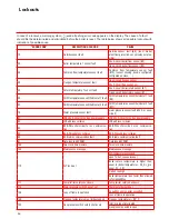
Page 44: ...or thermostat 1 fault DHW temperature sensor thermostat 1 fault B3 52 DHW temperature sensor thermostat 2 fault DHW temperature sensor thermostat 2 fault B31 78 Water pressure sensor fault water pressure sensor fault short or open circuit 81 LPB short circuit or no bus power supply LPB short circuit or no bus power supply 82 LPB address collision LPB address collision 83 BSB Wire short circuit or ...

Page 45: ...eter stick 322 Water pressure 3 too high Water pressure on input H3 too high 323 Water pressure 3 too low Water pressure on input H3 too low 324 Same sensor Input BX Same sensor Input BX 330 Sensor input BX1 no function Sensor input BX1 no function 331 Sensor input BX2 no function Sensor input BX2 no function 332 Sensor input BX3 no function Flue gas sensor not programmed correctly 353 Cascade flo...

Page 46: ...ture ºC Resistance Ohm NTC 1kȍ temperature sensor outdoor sensor NTC 10kȍ temperature sensor flow return flue gas DHW and header sensor The diagrams show the sensor va lues for all boiler sensors and optio nal sensors available in accessory kits The diagrams contain average values as all sensors are liable to tolerances When measuring the resistance va lues the boiler should always be switched off...

Page 47: ...0 EN 55014 1 2 EN 61000 3 2 3 EN 60 335 1 2 And in accordance with the guidelines of directives 92 42 EEC boiler efficiency directive 2009 142 EEC gas appliance directive 2006 95 EEC low voltage directive 2004 108 EEC EMC directive This product is designated with CE number CE 0063CM3576 1 EN 15502 1 EN 55014 1 2 EN 61000 3 2 3 EN 60 335 1 2 Kerkrade 29 07 2015 A J G Schuiling Plant Manager GB ...

Page 48: ...Note ...

Page 49: ... ENERGY SYSTEMS 96R Walton Road East Molesey Surrey KT8 0DL Tel 020 8783 3050 0870 7707747 Fax 020 8783 3051 0870 7707767 E Mail info stokvisboilers com Website www stokvisboilers com 420010685900 09 2 15 ErP ...

Reviews: