20
Installation
Air/Flue gas system
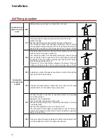
Combustion air
drawn from the
room
B23
([WHUQDOÀXHJDVH[KDXVW$LUGUDZQIURPWKHURRP
Combustion
air intake from
outside
C13
Air/exhaust gas routing through outside wall in the same
pressure range.
Exhaust gas/fresh air supply system through outside wall.
The Terminal outlets from separate combustion and air supply
FLUFXLWVVKDOO¿WLQVLGHDVTXDUHRIFPIRUERLOHUVZLWKDKHDWLQ
-
put to 70 kW and 100 cm with a heat input from 70 up to 100 kW.
C33
Flue gas exhaust and air suction duct from outside with roof ter-
minal in the same range of pressure.
The Terminal outlets from separate combustion and air supply
FLUFXLWVVKDOO¿WLQVLGHDVTXDUHRIFPDQGGLVWDQFHEHWZHHQ
WKHSODQHVRIWKHWZRRUH¿FHVVKDOOEHOHVVWKDQFPIRUERLOHUV
with a heat input below 70 kW.
A square of 100 cm and distance between the planes of the two
RUH¿FHVVKDOOEHOHVVWKDQFPZLWKDKHDWLQSXWDERYHN:
C43
,QGLYLGXDORUVKDUHGÀXHJDVH[KDXVWDQGDLUVXFWLRQWKURXJKÀXH
ducting built into the building.
C53
Flue gas exhaust leading outside and air suction duct through
external wall not in the same range of pressure
C63
Air and exhaust connection to separate tested and supplied
air / exhaust pipes.
%DVHPHQWÀRRULQVWDOODWLRQ
Air and exhaust venting via exterior wall.
Exhaust venting through heat insulated exhaust pipe or moistu-
re-resistant pipe.
Exhaust line (standing air layer) at exterior wall.
The terminals for the supply of combustion air and for the eva-
cuation of combustion products shall not be installed on opposite
walls of the building.
C83
)OXHJDVH[KDXVWWKURXJKLQGLYLGXDORUVKDUHGÀXHGXFWLQJEXLOW
into the building. Air suction through external wall


