background image

6

WARNING

Do not alter or deform electrical plug in any way.
Altering the plug to fit into an outlet of different con-
figuration may cause fire, risk of electrical shock,
product damage and will void warranty.

H.

Connect the power cord to the proper power
supply. The plug on the E112 is designed for
115VAC / 20 amp duty and the plug on the F112 is
designed for 208-240VAC / 15 amp duty. Check
the nameplate on your machine for proper supply.
The unit must be connected to a properly grounded
receptacle. The electrical cord furnished as part of
the machine has a three prong grounding type
plug. The use of an extension cord is not
recommended, if necessary use one with a size 12
gauge or heavier with ground wire. Do not use an
adapter to get around grounding requirement.

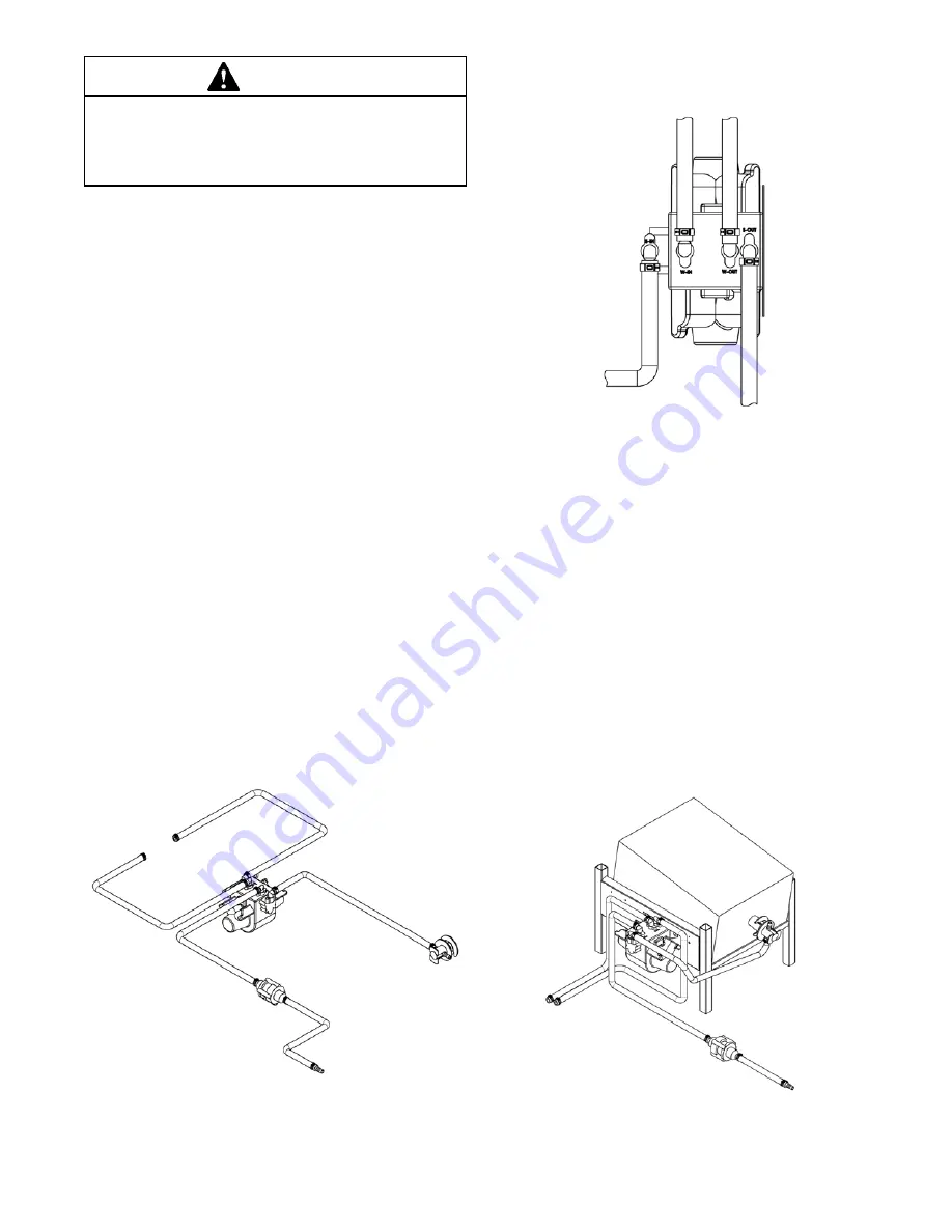
2.4 AUTO FILL PUMP INSTALLATION

The auto fill pump is powered by water and has a fixed orifice
that delivers water and syrup to the machine at an exact
ratio. The auto fill kit is designed for use with Bag In Box
(BIB) concentrated syrup.

Follow these instructions to properly install the brix pump

A.

Route the clear tubing with the BIB connector to
the BIB. If there is excess tubing, trim it and
reconnect it to the BIB connector.

B.

Route the water line tubing to the shutoff valve of the
water supply. Trim excess tubing and connect it to
the shutoff valve.

C.

Route the water line and syrup line tubing (3/8”
braided tubing) from the pump to the machine.

to

machine

water

inlet

to

BIB

Figure 2-4 Auto Fill Pump Tubing Layout

water outlet

to machine

water inlet

from shutoff

valve

syrup outlet

to machine

syrup inlet

from BIB

this side of

pump is

mounted to

the BIB shelf

Figure 2-5 Top View of Pump

Figure 2-6 Auto Fill Pump Kit

D.

Route the water line tubing to the tube exiting the
rear panel. Trim excess tubing and connect.

E.

Route the syrup line to the tubing connected to the
adapter on the hopper cover. Trim excess tubing
and connect.

F.

Check that the clear tubing coming out of the rear
panel is connected to the plug in the hopper cover.
If not, connect it using a clamp in the kit.

G.

Check that all tubing connections are properly
clamped, fittings are tightened and the tubing is not
kinked.

Summary of Contents for E112-LJ

Page 1: ...Model E112 LJ F112 LJ OPERATORS MANUAL Manual No 513643 Feb 2010...

Page 2: ......

Page 3: ...built prior to date of change DO NOT ATTEMPT to operate the machine until instructions and safety precautions in this manual are read completely and are thoroughly understood If problems develop or q...

Page 4: ...ecific safety information the following safety defini tions are provided to assist the reader The purpose of safety symbols is to attract your at tention to possible dangers The safety symbols and the...

Page 5: ...3 RemovingMixFromMachine 8 3 4 Disassembly of Machine Parts 8 3 5 Cleaning and Sanitzing the Machine Parts 9 3 6 Assembly of Machine 10 3 7 Sanitizing 11 3 8 FreezeDownandOperation 11 3 9 MixInformati...

Page 6: ......

Page 7: ...are gravityfed Themachinesareequippedwithfullyautomatic controls to provide a uniform product This manual is designedtohelpqualifiedservicepersonnelandoperators with the installation operation and mai...

Page 8: ...2 Figure 1 2 Specifications E112 F112 1 2 SPECIFICATIONS...

Page 9: ...Production Capacity 18 GPH 68 15 liters 24 GPH 90 87 liters 6 000 Btu hr 8 600 Btu hr 1 3 hp 3 4 hp Air cooled units require 3 7 6 cm air space on both sides or 4 10 2 cm air space in back for side b...

Page 10: ...4...

Page 11: ...dvise the carrier within 10 days and request inspection The customer must place claim for damages and or shortages in shipment with the carrier Stoelting cannot make any claims against the carrier 2 3...

Page 12: ...oncentrated syrup Follow these instructions to properly install the brix pump A Route the clear tubing with the BIB connector to the BIB If there is excess tubing trim it and reconnect it to the BIB c...

Page 13: ...en disconnected G Donotoperateunderunsafeoperatingconditions Neveroperatethemachineifunusualorexcessive noise or vibration occurs 3 2 OPERATING CONTROLS AND INDICATORS Before operating the machine it...

Page 14: ...s 3 3 REMOVING MIX FROM MACHINE To remove the mix from the machine refer to the following steps A Wash rinse dryandsanitizehandsbeforestarting B Turn the water line lever to the Off position C Place t...

Page 15: ...ve the auger assembly from the freezing cylinderandremovetheaugerblade Removethe rear seal and o ring from the auger L Remove the drain tray drip tray and drip tray grid M Removethehoppercoveranddisco...

Page 16: ...l Gel to the o ring C Assemble the rear seal onto the auger with the large end of the seal to the rear Lubricate the hex end of the auger with a small amount of spline lubricant D Installtheplasticaug...

Page 17: ...r Allow sanitizer to contact the surfaces to be sanitized for 5 minutes Any sanitizer must beusedonlyinaccordancewiththemanufacturer sinstruc tions In general sanitizing may be conducted as follows A...

Page 18: ...use highly abrasive materials as they will mar the finish 3 11 PREVENTIVE MAINTENANCE Stoelting recommends that a maintenance schedule be followedtokeepthemachinecleanandoperatingproperly B DAILY 1 Th...

Page 19: ...machine NOTE If the machine does not require cleaning and sani tizing turn it off and dispense enough product so that the mix level in the hopper is below the long probe If the mix level is above the...

Page 20: ...rical supply source D Clean thoroughly with a warm water detergent all parts that come in contact with the mix Rinse in clean water and dry parts Do not sanitize NOTE Do not let the cleaning solution...

Page 21: ...TROUBLESHOOTING 4 1 LIGHT INDICATORS The machine has two lights that will alert the user if a problem occurs an ADD MIX light and a Diagnostic Light The ADD MIX light will flash to alert the operator...

Page 22: ...install 2 Rear seal missing or damaged 2 Check or replace 3 Seal o ring missing damaged or installed incorrectly 3 Check or replace 4 Worn or scratched auger shaft 4 Replace auger shaft 1 Front door k...

Page 23: ...1 1 324141 Decal Caution Rotating Blades 1 1 324208 Decal Attention Refrigerant Leak Check 1 1 324393 Decal Stoelting Swirl Logo 1 1 324509 Decal Cleaning Instructions 1 1 324548 Decal Adequate Ventil...

Page 24: ...624645 624644 336551 2183099 570196 624545 625310 E112 2202181 F112 2202068 2183444 E112 2187600 F112 2187941 E112 2183854 F112 2183751 666786 624678 2187188 5 2 AUGER SHAFT AND FACEPLATE PARTS 21834...

Page 25: ...tom 5 Pack 1 1 624645 5 O Ring Spigot Body Top 5 Pack 1 1 624678 5 O Ring Rear Seal Black 5 Pack 1 1 625310 Quad Ring Front Door Black 1 1 630053 Rod Torque Actuator 1 1 666786 Seal Rear Auger Black 1...

Page 26: ...Description E112 LJ F112 LJ 396244 Gasket Freezer Base 1 417006 Grid Drip Tray Metal 1 1 624607 5 O Ring Mix Inlet 5 Pack 2 2 744254 Tray Drip 1 1 744281 Tray Drain 1 1 2177315 Cover Hopper 1 1 21879...

Page 27: ...nnector Bag In Box 1 375645 Fitting 3 8 x 3 8 1 538463 Nut 2 600930 Pump Brix 1 616116 Water Regulator 1 644359 Screw 10 32 x 1 2 2 739126 Tie Wrap 15 10 739127 Tie Wrap 7 2 756221 Tubing 3 8 Clear 3...

Page 28: ...22...

Page 29: ...f the affected component from into the equipment Those obligations remedies are subject to the conditions that Buyer a signs and returns to Stoelting upon installation the Warranty Registration Card f...

Reviews: