background image

9

AFTER SALES SUPPORT

1300 886 649

[email protected]

AUS

MODEL: STR-C   PRODUCT CODE: 49186   05/2015

Product Overview (Cont.)

Control panel layout

6

9

7

8

4

5

3

2

1

 Cooktop power on/off button

 Safety lock button

 Timer button

+

 Up / Value increase button

-

 Down / Value decrease button

 Rear left-hand cooking zone select button

 Rear right-hand cooking zone select button

 Front right-hand cooking zone select button

 Front left-hand cooking zone select button

Scope of delivery

Ceramic cooktop
Installation hardware (not shown):

4x Hob fixing brackets 
4x ST4*33 Zinc tapping screws  
Sealing tape

Instruction manual (not shown)
Quick start guide (not shown)
Warranty certificate (not shown)

Summary of Contents for STR-C

Page 1: ...N13275 AFTER SALES SUPPORT 1300 886 649 info tempo org AUS MODEL STR C PRODUCT CODE 49186 05 2015 Model Number STR C Ceramic Cooktop IM Version No V1 4 Issue Date 10 March 2015 INSTRUCTION MANUAL ...

Page 2: ...ing to buy a STIRLING product All products brought to you by STIRLING are manufactured to the highest standards of performance and safety and as part of our philosophy of customer service and satisfaction are backed by our comprehensive 3 Year in Home Warranty We hope you will enjoy using your purchase for many years to come ...

Page 3: ...DUCT CODE 49186 05 2015 Contents 02 Welcome 04 Warranty Details 05 General Safety Instructions 08 Product Overview 10 Installation 16 Getting Started 17 Instructions 23 FAQs Troubleshooting Guide 24 Other Useful Information 27 Repair and Refurbished Goods or Parts Notice ...

Page 4: ...e for parts and labour The benefits conferred by this warranty are in addition to all rights and remedies in respect of the product that the consumer has under the Competition and Consumer Act 2010 and similar state and territory laws Our goods come with guarantees that cannot be excluded under the Australian Consumer Law You are entitled to a replacement or refund for a major failure and to compe...

Page 5: ...e is going to be used for prolonged periods of time additional ventilation may be required If in doubt about your ventilation requirements consult your qualified installer Cables Do not allow electrical fittings or cables to come into contact with areas on the cooktop that get hot Curtains Do not install the cooktop next to curtains or soft furnishings Damaged cord If the power cord is damaged it ...

Page 6: ...hotplate to warm up plates Do not overload Do not put pots or pans weighing over 25kg on the cooktop To protect against the risk of electric shock do not touch the cooktop with wet hands or feet or when bare footed During use Do not stare at the cooktop elements when they are in use Frying food When frying food on the cooktop check constantly and ensure the oil is not overheating and becoming a fi...

Page 7: ... in such conditions could cause fire or electrocution In case of damage contact our after sales support centre using the details at the bottom of this page Do not use when faulty Do not use the cooktop in the event of a technical fault Any faults must be fixed by an appropriately qualified and authorised person Contact our after sales support line for advice Liability We assume no liability for an...

Page 8: ...6 649 info tempo org AUS MODEL STR C PRODUCT CODE 49186 05 2015 Product Overview Ceramic cooktop layout A 1200W Cooking zone 145mm Ø diameter B 1800W Cooking zone 180mm Ø diameter C Control panel see opposite for details A B C B A ...

Page 9: ...se button 5 Down Value decrease button 6 Rear left hand cooking zone select button 7 Rear right hand cooking zone select button 8 Front right hand cooking zone select button 9 Front left hand cooking zone select button Scope of delivery Ceramic cooktop Installation hardware not shown 4x Hob fixing brackets 4x ST4 33 Zinc tapping screws Sealing tape Instruction manual not shown Quick start guide no...

Page 10: ...5 C under bench access must be restricted in order to avoid a hazard Installation Unpacking the appliance This product has been packaged to protect it against transportation damage Unpack the appliance and remove all packaging materials from around the cooktop Keep all packaging materials until you have made sure your new ceramic cooktop is undamaged and in good working order The carton is recycla...

Page 11: ... the dimensions given in Fig 1 below To avoid a hazard due to high surface temperatures access to the underside of the hob must be restricted This can be done via a board as per E in Fig 1 below Installation Cont 1 Benchtop 2 Screw 3 Bracket 4 Hob 5 Hob seal Ventilation slot must be between 30mm and 70mm and cannot exceed 70mm 50mm MIN od block Fig 1 0 750mm 580m m 49 m m 68mm Wood block 564mm 494...

Page 12: ...und the hob prevents liquid from entering the cabinet Follow the instructions below in order to correctly apply this seal Detach the backing strip from sealing tape but ensure that the transparent adhesive still adheres to the seal itself Turn over the hob and correctly position the sealing tape under the edge of the hob ensuring that the outer part of the seal perfectly matches the outer edge of ...

Page 13: ...ide of the cooktop as illustrated in Fig 4 Using the screws provided affix the bracket to the cooktop and then tighten the screws securely Fig 5 This is very important The other end of the bracket should be located underneath the benchtop to secure the hob in position Installation Cont Fig 3 Mounting slots Fig 5 Fig 4 NOTE Fig 4 and Fig 5 illustrate how to affix the brackets to the cooktop At this...

Page 14: ...tioned that no point can reach a temperature 50 C higher than the ambient temperature Also check that the supply system has an effective earth connection and corresponds to the standards in force and that the breaker can be reached easily when the appliance is installed If the appliance you have purchased is not fitted with a mains power lead a power lead resistant to a temperature of at least 90 ...

Page 15: ...ons must be in accordance with the diagram located on the bottom of the cooktop This appliance must be wired into a 30A double pole switched fused spur outlet having 3mm contact separation and placed in an easily accessible position adjacent to the appliance It should not be located above the appliance and no more than 1 25m away from it The cable can be looped if necessary but make sure that is n...

Page 16: ...ng transport and storage Dry thoroughly To help eliminate any new smell that exists and evaporate any humidity that may have formed on the heating elements during transit switch on one cooking zone at a time and let it heat up for 5 minutes at the maximum setting Place a saucepan filled half full with cold water on each zone as you burn it off Do not burn off more than one zone at a time Any odour...

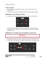
Page 17: ...ress the Power On Off button to switch on the cooktop Fig 8 The appliance will beep once and all cooking zone indicators will light up briefly They will then go out indicating that the cooktop has entered stand by mode Switching on a cooking zone and setting a power level Fig 8 Fig 9 A B IMPORTANT You must select a cooking zone within 10 seconds of switching on the cooktop Press the select button ...

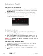
Page 18: ...one is still hot Fig 10 Residual heat indicator After a zone is switched off the corresponding heat level display will show the letter H Fig 10 which indicates that the temperature of the zone is still high enough to cause injury When the temperature of the zone has dropped the letter H will go out but it is still possible to burn yourself on a cooktop zone so take due care IMPORTANT The residual ...

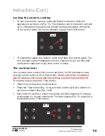
Page 19: ...r from the display and you are then able to adjust the heat level of any zone on the cooktop The cooktop timer Your cooktop has a timer which you can set from 1 to 99 minutes for each cooking zone to switch it off at the set time At the end of the countdown period a buzzer will sound and the cooking zone will be switched off To stop the buzzer press the Timer button Select the cooking zone and hea...

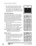
Page 20: ...ing to the set lower level The boost time at maximum power for each power level is listed in Table 1 Press the select button for the cooking zone you want to use Press the Up button to set the heat level to 9 then press it again and wait until the display alternates between 9 and A Auto Now press the Down button repeatedly to set the lower heat level for continued cooking NOTE Pressing the Down bu...

Page 21: ...one advice on suitable cookware follows on the next page Preferably cover pots and pans with a lid to permit cooking at a lower heat Always place a filled pot on the cooking zone first before switching it on Do not heat up a cooking zone without pot or pan or with an empty pot Take care when cooking to prevent liquids spilling onto the ceramic cooktop surface When boiling food use as little water ...

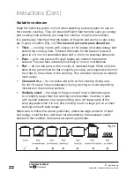
Page 22: ...rface They are also unsteady and likely to rock or overbalance Flat do not use pans with a convex or recessed base When cold the base of the pan should be flat or slightly concave as it expands when hot to sit flat on the surface of the cooktop This will allow the heat to transfer more easily Clean and dry do not place wet pots on the cooktop during use Do not lift up pot lids unnecessarily during...

Page 23: ... heated The remaining area remains relatively cool What does the H mean that sometimes lights up next to the cooking zone buttons The cooking zones retain some heat after they are switched off The H next to a cooking zone button is a residual heat indicator which shows that the relevant cooking zone is still hot Do not touch any cooking zones that still have an H displayed Knowing which cooking zo...

Page 24: ...eposit Sugar or food liquid containing sugar Immediately Ceramic cooktop scraper Aluminium foil or cling wrap Immediately Ceramic cooktop scraper Fat splashes When cooled down Ceramic cooktop cleaner Water splashes or water rings When cooled down Ceramic cooktop cleaner Other Useful Information CAUTION Always allow the cooktop surface to cool before cleaning the cooktop You may find it easier to c...

Page 25: ...rmation Cont Spare parts Our after sales support centre stocks the following spare parts for the STR C STIRLING Ceramic Cooktop To purchase a part call the centre on 1300 886 649 or email us at info tempo org Ceramic glass cooktop Connection box Bottom shell Display panel Fixing screw bolt Hotplate 1800W Hotplate 1200W Hotplate bracket Hotplate spring Insulation panel M6 Nut PCB box PCB mat PCB pa...

Page 26: ...ocal regulations regarding the disposal of electrical consumer goods and dispose of it appropriately for recycling Contact your local authorities for advice on recycling facilities in your area Other Useful Information Cont Technical specifications Rated Voltage 240V AC 50Hz Max Rated Inputs 6 0kW Power 1200W 145mm and 1800W 180mm Dimensions mm 580 W x 510 D x 50 H 68mm H with terminal board Cut o...

Page 27: ...f your stored data may be lost We recommend you save this data elsewhere prior to sending the product for repair You should also be aware that rather than repairing goods we may replace them with refurbished goods of the same type or use refurbished parts in the repair process Please be assured though refurbished parts or replacements are only used where they meet ALDI s stringent quality specific...

Page 28: ... your expectations make sure to contact our After Sales Support Centre on 1300 886 649 before returning it to the store for a refund For an electronic copy of this manual go to www stirlingappliances com au and download a copy Instruction Manual Revision Index Version No Issue Date Description V1 0 19 January 2015 Original release V1 1 30 January 2015 Illustration updates V1 2 17 February 2015 Com...

Reviews: