INSTALLATION
Installation
www.stiebel-eltron.com
WPL ICS classic | WPL IKCS classic |
15
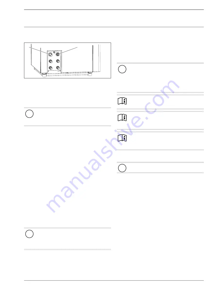
10.8 Condensate drain and overpressure valve
D
00000
69
08
0
1
2
1 "Outlet condensate drain" connection
2 "Safety valve drain" connection
On its l.h. side the appliance is equipped with the "Outlet conden-
sate drain" connection.
f
f
Connect a condensate line to the "Outlet condensate drain"
connection.
!
Material losses
To ensure the condensate drains off correctly, never kink
the condensate line. If necessary, create a loop.
f
f
Route the condensate line with a sufficient fall.
f
f
Route the condensate into a drain near the floor. When doing
so, ensure the drain is adequately ventilated, e.g. free dis-
charge into a trap. Use a condensate pump if there is insuffi-
cient fall.
f
f
Check the position of the condensate pump. The condensate
pump must fully rest on the floor.
Pressure relief valve drain
On the l.h. side of the appliance, the "Safety valve drain" connec-
tion routes the pressure relief valve discharge hose out of the
casing. Ensure that draining water can run off freely.
10.9 Checking the condensate drain
After routing the condensate drain hose, check that the condensate
can drain off correctly. For this, proceed as follows:
f
f
Pour water onto the evaporator, which will then flow into the
defrost pan. Observe the maximum condensate drain capac-
ity of 6 l/min.
f
f
Check whether the water is draining off through the conden-
sate drain hose.
10.10 Temperature controller for underfloor heating
systems
!
Material losses
In order to prevent excessively high flow temperatures
in the underfloor heating system causing damage in the
event of a fault, we always recommend using a temper-
ature controller to limit the system temperature.
10.11 Filling the heating system
Heating water quality
Carry out a fill water analysis before filling the system. This analy-
sis may, for example, be requested from the relevant water supply
utility.
!
Material losses
To avoid damage as a result of scaling, it may be neces-
sary to soften or desalinate the fill water. The fill water
limits specified in chapter "Specification / Data table"
must always be observed.
f
f
Recheck these limits 8-12 weeks after commission-
ing and as part of the annual system maintenance.
Note
f
f
Never add inhibitors or other additives (e.g. glycol)
to the fill water.
Note
If conductivity is >1000 μS/cm, desalination treatment is
recommended as the best option for preventing corro-
sion.
Note
Suitable appliances for water softening and desalinating,
as well as for filling and flushing heating systems, can be
obtained from trade suppliers.
Filling the heating system
!
Material losses
Never switch on the power before filling the system.
In the delivered condition, the diverter valve of the MFG is posi-
tioned at the centre. This ensures the heating and DHW circuits are
filled equally. When the power is switched on, the diverter valve
automatically moves into the heating position.
If you intend to fill or drain the system later, first return the diverter
valve to its centre position.
For this, enable controller parameter DRAIN HYD in the menu
DIAGNOSIS / RELAY TEST SYSTEM.
f
f
Fill the heating system via the drain.
f
f
After filling the heating system, check the connections for
tightness (visual and physical inspection).


