background image

Z001007/0_4_September 2007

Page NOISE ATTENUATION-5

NOISE ATTENUATION

INSTALLATION INSTRUCTION

14. 4. NOISE-ABSORBING MATERIAL

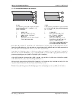
ill. 14/5

noise-absorbing material for engine hood made

of wood (plywood 5/8" / 15 mm) or  1/12"

(2 mm) steel plate

1

engine hood

2

lead sheet, 0,5 line (1 mm)

3

mineral cotton, 2" (50 mm)

4

plastics foil

5

perforated aluminum sheet, 0,5 line

(1mm), perforation 20%

ill. 14/6

noise-absorbing material for engine hood made

of  1/12" (2 mm) steel plate or wood (plywood

5/8" / 15 mm)

1

engine hood

2

flame-proof absorbing mat,

e.g.: "Porolon", "Revertex

Acoustics" or Baryfoil.

3

flame-proof reflecting  sound-

absorbing foil (ferruginous PVC,

thickness 1/10" / 2,5 mm)

15% of the engine-sided surface to

be provided with absorbing mat.

Noise-absorbing material on ill. 14/5 shows a construction for extremely high insulation requirements, also

containing a lead sheet layer. This construction is very stable and is also recommended for engine compartments

the walls of which are for different reasons weaker than recommended.

Under the same conditions as shown on ill. 14/5, one single layer of a flame-proof insulating mat, e.g. "Porolon",

"Revertex Acoustics" or "Barifoil" may be glued directly onto the inner side of the engine protection. This noise-

absorbing material will in many cases be sufficient. Use contact glue.

Such material requires little space and is easy to handle. All surfaces to be glued must be completely grease-

and moisture-free, to achieve and maintain good adherence.

Many different noise-absorbing materials are available on the market, but only materials meeting the current

requirements as to fire protection and noise reduction may be used.

Finished noise-absorbing mats with absorbing layers for soundproofing are also available on the market.

Summary of Contents for 4 Cylinders

Page 1: ...yr motors com STEYR MOTORS GmbH Im Stadtgut B1 A 4407 Steyr Gleink AUSTRIA 4 CYLINDERS 6 CYLINDERS STEYR MARINE ENGINES INSTALLATION INSTRUCTION P N Z001007 0 4th Edition September 2007 4 CYLINDERS 6 CYLINDERS ...

Page 2: ...rawings There should also be enough space to permit an inward and outward lifting of the engine The installation is to be done in such a way that the engine is easily accessible for regular routine and maintenance works in order to avoid unnecessary maintenance costs for the owner Product description illustration and technical data When reference is made in this manual to a brand name a product nu...

Page 3: ...RIANTS ENGINE PROPULSION 5 ENGINE INSTALLATION 6 COOLING SYSTEM 7 FUEL SYSTEM 8 EXHAUST SYSTEM 9 AIR INTAKE AND VENTILATION 10 AUXILIARY PROPULSION 11 SAFETY COVERS 12 BILGE PUMPS 13 CABIN HEATING 14 NOISE ATTENUATION 15 CONTROL STATION 16 ELECTRICAL EQUIPMENT AND INSTRUMENTS 17 DRILL TEMPLATES 18 APPENDIX PREFACE ...

Page 4: ...Z001007 0_4_September 2007 VERSIONS OF MANUAL Version Date Modification 1 0 01 11 1998 First edition 2 0 01 03 1999 Modification 3 0 01 04 2006 Modification 4 0 01 09 2007 Modification PREFACE ...

Page 5: ... his country before beginning works 1 2 RESPONSIBILITIES OF BOAT OWNERS As a boat owner you have certain responsibilites to others You are legally responsible for all occupants of your boat Show all assistants the location of the emergency equipment and how to use it Your are required by law to have aboard one proper life jacket for each person plus one approved throwable device for man overboard ...

Page 6: ...GENERAL Page GENERAL 2 Z001007 0_4_September 2007 INSTALLATION INSTRUCTION THIS PAGE IS INTENTIONALLY BLANK ...

Page 7: ...ficient 4 2 4 SAFETY IN DEALING WITH FUEL AND OIL 5 2 5 LIST OF FUEL AND OIL 6 2 5 1 Manuals 7 2 6 SI SYSTEM 8 2 7 ABBREVIATIONS 9 2 8 GENERAL INFORMATION ON SAFETY 10 2 9 GUIDELINES FOR DAMAGE PREVENTION 10 2 10 LEGAL RULES 10 2 11 DISPOSAL OF AUTOMOTIVE WASTE PRODUCTS 10 2 12 SAFETY IN DEALING WITH FUEL AND OIL 11 2 13 MEASURES IN CASE OF ACCIDENTS 11 2 GENERAL INFORMATION ON INSTALLATION TABLE ...

Page 8: ...GENERAL INFORMATION Page GENERAL INFORMATION 2 Z001007 0_4_September 2007 INSTALLATION INSTRUCTION 2 GENERAL INFORMATION ON INSTALLATION NOTES ...

Page 9: ...ossible weight distribution balance should always be the aim ATTENTION ON ACCOUNT OF THE RISK OF EXPLOSION AND FIRE THE FUEL TANKS BATTERIES AND ENGINES ARE TO BE PLACED IN WELL VENTILATED COMPARTMENTS SEPARATED FROM EACH OTHER MORE DETAILS WILL FOLLOW 2 2 ACCESSIBILITY During assembly of the engine take greatest care as to accessibility for service works An easy exchange of pump wheels oil filter...

Page 10: ...ors Overlapping of the individual sectors with the actual waterline will resultindifferentfieldswithdifferentvolumes andby adding these volumes the displacement of water can be calculated For the accuracy of calculation the number of subdivisions is determining e g Simpson s First Rule Murphys Law The displacement of water can also be determined by the BLOCK COEFFICIENT which however is more inacc...

Page 11: ... not extinguish with water Use carbon dioxide extinguishers or powder extinguishers Notify the fire department In case of spilling such materials e g while refueling these are to be absorbed with sand earth or suitable binding agents and to be eliminated Attention To avoid health troubles the following items are to be considered Avoid direct contact with dangerous materials Change clothing contami...

Page 12: ...e surface sealing 5900 300 ml cartridge construction adhesive 620 50 ml flask construction adhesive 262 50 ml flask contact grease 100 ml tube corrosion protection spray 400 ml can corrosion protection wax 120 ml can grease STABURAX NBU4 1 kg can fuel rust protection additive 5 lt can electric contact spray silver varnish RAL 9006 1 lt can hardener varnish 0 5 lt can dilution for varnish 5 lt can ...

Page 13: ...TEYR 94 td diesel marine P N Z 001023 0 STEYR 144 vti td diesel marine P N Z 001005 0 STEYR 164 td diesel marine P N Z 001015 0 STEYR 174 vti diesel marine P N Z 001011 0 STEYR 166 td diesel marine P N Z 011796 1 STEYR 236 FDE P N Z 011796 0 STEYR 236 td diesel marine P N Z 011796 1 Z011769 2 STEYR 246 td diesel marine P N Z 011800 0 STEYR 256 td diesel marine P N Z 011810 0 STEYR 266 td diesel ma...

Page 14: ...watt hour ft2 square foot yd2 square yard units of volume units of energy m3 cubic meter kW kilowatt cm3 cubic centimeter PS horsepower dm3 cubic decimeter mm3 cubic millimeter ft3 cubic foot yd3 cubic yard l liter units of measure units of temperature t ton K degree Kelvin kg kilogram C degree centigrade g gram units of force units of time N Newton h hour kN kilo Newton min minute daN deca Newton...

Page 15: ... Page GENERAL INFORMATION 9 GENERAL INFORMATION INSTALLATION INSTRUCTION 2 7 ABBREVIATIONS ill illustration Cu copper HGrp master unit Max maximum OT top dead center PTO POWER TAKE OFF on crankshaft SW head width wc water column ...

Page 16: ...ake care not to apply them on the surface of optical systems Lubricants should form a thin film on the surface surplus lubricants must be removed 2 10 LEGAL RULES The following rules and guidelines are valid in Austria For other countries follow the local regulations 2 11 DISPOSAL OF AUTOMOTIVE WASTE PRODUCTS Used fuel and oil is to be collected in separate containers to permit an eventual subsequ...

Page 17: ...d ATTENTION To avoid health troubles the following items are to be considered Avoid direct contact with dangerous materials Change clothing contaminated with dangerous materials as soon as possible Do not keep oily cloths in your overalls Clean oily parts of your body only with skin care products never use abrading sand or solvent Never put working materials into drinks bottles 2 13 MEASURES IN CA...

Page 18: ...GENERAL INFORMATION Page GENERAL INFORMATION 12 Z001007 0_4_September 2007 INSTALLATION INSTRUCTION THIS PAGE IS INTENTIONALLY BLANK ...

Page 19: ... for plastic tube 4 3 3 4 Checking of plug connections 5 3 3 5 Assembly of Raufoss plug systems 5 3 3 6 Sealing of screwed pipe joints 5 3 3 7 Tightening torque 6 3 3 8 Pipe relaying 7 3 4 TIGHTENING TORQUES 8 3 5 CHECKING OF TORQUE WRENCH 9 3 6 NONDESTRUCTIVE TESTING OF MATERIALS 9 3 7 USE OF ADHESIVE AND SEALING MATERIALS 9 3 8 SOLVENT FREE SEALING MATERIALS 9 3 8 1 General directions for use 10...

Page 20: ...QUALITY DIRECTIVES Page QUALITY DIRECTIVES 2 Z001007 0_4_September 2007 INSTALLATION INSTRUCTION 3 QUALITY DIRECTIVES FOR ASSEMBLY NOTES ...

Page 21: ...ingreliability andwhichareapprovedwithregardtotheireffectiveness irrespectiveofthevehicle Incase of an exchange such components may be replaced by design approved parts only 3 1 SPECIFICATION OF SPARE PARTS Your STEYR diesel engine with direct fuel injection has been designed for high output Only use GENUINE STEYR spare parts to avoid any loss of efficiency You therefore should insist on the known...

Page 22: ...is done by repeated screwing down of the union nut for approx 1 turn After this disengage the union nut and check if the cutting ring s edge has penetrated the outer skin of the tube and if the collar in front of the edge is visible If necessary the union nut is to be tightened once again It is insignificant if the cutting ring at the end of tube can be turned After completion of the connection as...

Page 23: ...ST NOT BE DISMANTLED Before insertion mark the plastic tube at gape x depending on its diameter and then push it into the socket up to this mark Afterwards check clamping of the plastic tube by a quick traction in direction B NOTE THE PLASTIC TUBE MUST NOT TURN IN THE SOCKET 3 3 6 Sealing of Screwed Pipe Joints Before assembly of the plug connections thinly coat the outer side of the cutting ring ...

Page 24: ...Torque 6 10 12 Nm 18 65 80 Nm cutting ring connections for plastic tubes Tube Torque 6 16 20 Nm 8 25 30 Nm ATTENTION ABSOLUTELY USE SLIP ON SLEEVES clamping ring connections for plastic tubes Tube Torque 12 30 50 Nm screwed pipe joints in aluminum housings Thread Torque M 10x1 20 Nm M 12x1 5 26 Nm M 14x1 5 28 Nm M 16x1 5 35 Nm M18x1 5 38 Nm M22x1 5 40 Nm M26x1 5 50 Nm ...

Page 25: ...or plastic tubes even of a non twisting relaying Grooves or other damages of the tube surface are to be avoided Damaged tubes are to be exchanged If plastic tubes are clamped with cable bond it is to be ensured that the tubes are not constricted Relaying is to be done with sufficient safety distance to chafe marks In case of possible chafing use an edge protection or a spacer ...

Page 26: ...00 1650 M 27 1050 1500 1800 M 30 1150 1600 1950 M 30 1350 1850 2250 M 30 1450 2000 2400 nominal Ø nominal Ø nominal Ø M 8x1 22 30 36 M 8x1 25 35 42 M 8x1 27 38 45 M 10x1 25 42 59 71 M 10 x 1 25 49 68 82 M 10x1 25 52 73 88 M 12x1 25 76 105 130 M 12x1 25 88 125 150 M 12x1 25 95 135 160 M 12x1 5 72 100 120 M 12x1 5 83 115 140 M 12x1 5 90 125 150 M 14x1 5 120 165 200 M 14x1 5 140 195 235 M 14x1 5 150 ...

Page 27: ... of screw joints hence not required Anaerobic sealing materials are used for securing fixing and sealing and will only harden with exclusion of air Sealing material containing solvent Their volatile ingredients will cause a loss of volume during hardening For repair works their exhaust period is to be considered If such sealing material is used the workshop manual will contain a particular referen...

Page 28: ...nimum Directions for securing S Indication SM Medium tight Securing the connection can be loosened without problems Indication SF Tight Securing the connection is difficult to loosen Application Screw joints Fixing procedure In general it is sufficient to apply the synthetic on the screw thread If screws are screwed into socket threads only wet the taphole in order to let the air escape during scr...

Page 29: ...er 2007 Page VARIANTS ENGINE PROPULSION 1 VARIANTS ENGINE PROPULSION INSTALLATION INSTRUCTION 4 VARIANTS ENGINE PROPULSION TABLE OF CONTENTS 4 1 VERSIONS FOR 6 CYL MARINE ENGINES 3 4 2 VERSIONS FOR 4 CYL MARINE ENGINES 6 ...

Page 30: ...VARIANTS ENGINE PROPULSION Page VARIANTS ENGINE PROPULSION 2 Z001007 0_4_September 2007 INSTALLATION INSTRUCTION 4 VARIANTS ENGINE PROPULSION NOTES ...

Page 31: ... VARIANTS ENGINE PROPULSION 4 1 VERSIONS FOR 4 CYL MARINE ENGINES Inborder i e ZF 45 Marinegear Down angle Bobtail Version Innenborder i e ZF 63 Marinegear Equipment with side mounted raw water pump with side mounted raw water pump power steering pump For exact installation dimensions see chapter 17 Drill templates ...

Page 32: ...ANTS ENGINE PROPULSION 4 Z001007 0_4_September 2007 INSTALLATION INSTRUCTION Equipment Bobtail B Direkt gearbox A down angle gear box Parallel offset gearbox Lifeboat Engine For exact installation dimensions see chapter 17 Drill templates ...

Page 33: ...N 5 VARIANTS ENGINE PROPULSION INSTALLATION INSTRUCTION Stern Drive Jet Drive TYPE Mercury Alpha Bravo I II III Volvo DP 290 Volvo DP 290 Hydraulic SX Stern Drive TYPE Alamarin Hamilton Castoldi For exact installation dimensions see chapter 17 Drill templates ...

Page 34: ...STRUCTION 4 2 VERSIONS FOR 6 CYL MARINE ENGINES For exact installation dimensions see chapter 17 Drill templates Inborder i e ZF 63 Marine gear Down angle with side mounted raw water pump with side mounted raw water pump power steering pump and front mounted auxiliary drive PTO Bobtail Version Equipment ...

Page 35: ...ANTS ENGINE PROPULSION INSTALLATION INSTRUCTION For exact installation dimensions see chapter 17 Drill templates Transmission Lifeboat Engine Equipment Bobtail B Direkt gearbox A down angle gear box Parallel offset gearbox i 2 5V shaft angle 12 i 2 0V shaft angle 12 ...

Page 36: ...er 2007 INSTALLATION INSTRUCTION For exact installation dimensions see chapter 17 Drill templates Stern drive Mercury Bravo II III Volvo DP 290 Stern Power Drive Volvo DP 290 ZF Hydraulic Pump Volvo SX Drive King Cobra Drive Type Jet Drive TYPE Alamarin Hamilton Castoldi Jet drive ...

Page 37: ... 3 ENGINE BASE 5 5 3 1 Engine Base on Synthetic Boats 5 5 4 SPACE FOR MAINTENANCE 5 5 5 ENGINE INCLINATION 6 5 6 LIFTING EYES 7 5 7 CHECKING OF ENGINE BASE 7 5 8 PROPELLER SHAFT FLANGE 8 5 9 ENGINE SUSPENSION 8 5 9 1 Adjustment of Engine on flexible engine supports 9 5 10 ELASTIC SHAFT COUPLING 10 5 11 STEP BEARING 10 5 12 ADJUSTMENT OF ENGINE DRIVE UNIT 11 5 13 TWIN INSTALLATION 12 5 14 SHAFT AND...

Page 38: ...3 5 15 3 Blade Surface 14 5 15 4 Sense of Rotation 14 5 15 5 Number of Blades 14 5 15 6 Axle Hub 14 5 15 7 Adjustment of Propeller Pitch 14 5 15 8 Space between Propeller and Boat 15 5 15 9 Sediments 15 5 15 10 Choice of Propeller 15 5 15 11 Cavitation 16 5 16 PROPELLER THRUST BEARING RESP STEP BEARING 16 5 ENGINE INSTALLATION TABLE OF CONTENTS ...

Page 39: ...r Coupling size depends on the maximum engine torque to be transmitted thetorquepeaksduetothedegreeofirregularityoftheengine andthealternatingmomentsoftorsionalvibration at critical speeds of the boat Based on a torsional vibration computation it must be checked whether the chosen coupling as well as dimensioning and arrangement of the unit could lead to undue torsional vibrations causing severe d...

Page 40: ...addition it should be considered not to drive too long at the critical speed range If a disconnectable coupling is used the admissible axial load of the crankshaft must not be exceeded 5 2 2 Universal Joint Shafts Principles Auniversaljointproduces amoreorlessstrongirregularityonthedrivingaxle dependingonthediffractionangle This irregularity is compensated by providing a second universal joint und...

Page 41: ...ce chart in the operating manual Also take care that there is enough space for lifting and lowering the engine Before beginning the assembly make sure that scale drawings for the engine and its equipment are available see appendix All necessary dimensions for assembly follow from the scale drawings e g the distance from the crankshaft centre to the engine bearers reversing gear bearers and to the ...

Page 42: ...ine must not be inclined downward in direction of the heat exchanger since such an installation could affect the cooling due to remaining air pockets When installing the engine with the flywheel side in direction of the bow the inclination in direction of the flywheel should be 3 at least Such an installation with inverted engine occurs with a miter gear During course A may be up to 3 larger and B...

Page 43: ...aring the engine base make sure that the upper contact surfaces of the bearers are parallel to the centre line of the propeller shafts and are not swung For assistance during assembly and checking of the engine base a short traversing slide with the same diameter as the propeller shaft may be used stern sided see ill 5 8 Through a bore 1 12 2mm diameter in the slide a 1 12 2 mm copper wire is stra...

Page 44: ...rame see ill 5 3 For an assembly with flexible engine mounts the overall height of the engine mounts is to be considered to achieve the proper installation height of the engine Height Adjustment recommended to achieve accurate alignment of the suspended unit When fitting mounts with height adjusters care must be taken to ensure that excessive bending forces are not imposed on the center spindle sc...

Page 45: ...Lift the engine at the front to such an extent that both front supports are released from the lower nuts of the mounts Lower the engine and adjust the nuts so that both engine supports sit simultaneously Same procedure at the rear side of the engine The engine foundation must be rigid enough to absorb the concentrated load After correct adjustment of the engine mounts the engine can be balanced by...

Page 46: ...propeller shaft is also to be mounted The elastic coupling should be situated between reversing gear and thrust bearing to avoid tensions between the parts 5 11 STEP BEARING If the distance between the supports a in ill 12 and 13 exceeds 6 1 2 ft 2 m a step bearing is to be mounted The correct distance between the step bearing and the engine is of utmost importance which requires a computation of ...

Page 47: ...r having finished the adjustment prepare supporting disks fitting between the engine reversing gear bearers and the rests on the engine Measure the distances and prepare steel disks to be ground to the dimensions found Make all bores for the bearers and screw on the engine and the reversing gear Take care that all setscrews for the high position are unscrewed so that the bearers do not rest on the...

Page 48: ...th dismantling Between propeller and stem bearing a min distance of 1 25 mm is to be kept in order to prevent the propeller from bucking against the stem bearing Before mounting the shaft its straightness is to be controlled Check by means of a dial gauge that the shaft flanges do not twist Max admissible axial fault 0 1 mm Before launching the boat make sure that a propeller with correct pitch an...

Page 49: ...ption that the propeller determines the speed but it is the combination of engine power with adapted hull and matching propeller The propeller diameter can be approximately computed based on the diagram enclosd but this only for water displacers Before using the diagram the max speed of the ship is to be computed Only use this diagram for an approximate computing of the diameter e g for determinin...

Page 50: ... blades are being used If much speed at low revolutions is required in particular on larger boats even propellers with more than three blades are used This should also be determined by specialists For the same boat and the same engine the diameter of a four blade propeller may be by 10 less than that of a three blade propeller On sailing boats often a two blade propeller is used which lessens the ...

Page 51: ...propellers with Fa F of 0 54 to 0 74 For gliding boats 4 blade propellers with Fa F of 0 54 to 0 74 may be considered Most propellers are made of bronze but propellers made of metal or aluminum are also available Various propellers with examples of application The maximum propeller diameter results from the shape of the hull The illustration shows a displacer but even for a glider the conditions a...

Page 52: ...etween reversing gear and thrust bearing is always to be installed in order to avoid axial tensions between the two thrust bearings With a shaft length exceeding the standard size a separate step bearing is to be installed The step bearing cannot take axial forces 1 thrust bearing 2 elastic coupling ill 5 22 2 bladefoldingpropellertobeaplied on sailing boats ill 5 21 2 blade propeller to be applie...

Page 53: ...N INSTRUCTION 6 1 SCHEME OF A RAW WATER COOLING WITH GEAR 3 6 2 SCHEME OF A RAW WATER COOLING WITH STERN DRIVE 3 6 3 RAW WATER PIPES 4 6 4 RAW WATER INLET AND BOTTOM VALVE 4 6 5 RAW WATER FILTER 5 6 6 COOLING WATER PIPES EXHAUST CONNECTION 5 6 COOLING SYSTEM TABLE OF CONTENTS ...

Page 54: ...COOLING SYSTEM Page COOLING SYSTEM 2 Z001007 0_4_September 2007 INSTALLATION INSTRUCTION 6 COOLING SYSTEM NOTES ...

Page 55: ...3 COOLING SYSTEM INSTALLATION INSTRUCTION 6 COOLING SYSTEM 6 1 SCHEME OF RAW WATER COOLING WITH GEARBOX 6 2 SCHEME OF RAW WATER COOLING WITH STERNDRIVE 1 raw water inlet 2 bottom valve 3 raw water filter 4 exhaust and raw water gate ill 6 1 ill 6 2 ...

Page 56: ... pump The hose should be designed with steel spiral otherwise the underpressure in the suction pipe may cause a collapse of the hose thus no more guaranteeing a sufficient natural water supply ill 6 3 1 raw water pick up 2 stop cock 3 hose Raw Water Pipes Dimensions in mm and inches suction pipe inside diameter suction pipe outside diameter hose bottom valve sea water pump inside diameter connecti...

Page 57: ...ust gases When designing the exhaust elbow particular importance was attached to a relatively high exhaust duct in order to avoid the entering of back wash In the adjoining exhaust pipe a splash flap is to be installed in addition In case of insufficient difference in level between exhaust gas outlet and sea water surface boad loaded a high riser exhaust elbow optional is to be installed See secti...

Page 58: ...COOLING SYSTEM Page COOLING SYSTEM 6 Z001007 0_4_September 2007 INSTALLATION INSTRUCTION THIS PAGE IS INTENTIONALLY BLANK ...

Page 59: ...Z001007 0_4_September 2007 Page FUEL SYSTEM 1 FUEL SYSTEM INSTALLATION INSTRUCTION 7 1 GENERAL 3 7 2 FUEL TANKS 4 7 3 MATERIALS 5 7 4 TWIN FUEL TANKS 5 7 5 FUEL PIPES 5 7 FUEL SYSTEM TABLE OF CONTENTS ...

Page 60: ...FUEL SYSTEM Page FUEL SYSTEM 2 Z001007 0_4_September 2007 INSTALLATION INSTRUCTION 7 FUEL SYSTEM NOTES ...

Page 61: ...y to store the tanks in a separate area in order to minimize as far as possible the risk of fire in case of an eventual fuel leakage For assembly of the fuel tanks proceed with greatest care to avoid leakage or water inlet STEYRMOTORSinsistthatawaterseperatorisfittedintothefuelsystembeforethefuelpump asdropsofwater in the fuel are ideal transporters of dirt and rust through narrow pipes One drop o...

Page 62: ...is case the fuel flowing back from the engine is pumped into the daily tank ill 7 2 1 water separator rate of flow 65 Brit gl h 300 l h 2 fuel stop cock 3 fuel pipe outside diameter 3 8 10 mm for a length of 20 ft 6 m For longer lines use a 1 2 12 mm pipe 4 inspection cover 5 filler socket cover 6 lead in sleeve made of fuel resistant rubber with drain possibility 7 air vent pipe diameter at least...

Page 63: ...rom the lower connecting pipe of the tank only valid for tanks with bottom drain An additional fuel filter or water separator is to be installed in front of the feed pump on the injection pump In case of a daily tank it is recommended to connect the fuel return pipe to this tank which reduces the filling intervals 7 5 FUEL PIPES Min inside diameter of the fuel filler socket should be 1 1 2 38 mm L...

Page 64: ...ata for fuel hoses synthetic rubber hose with plies of fabric size DN 8 resistant to Diesel fuel fire proof temperature range 30 bis 30 C operating pressure 145 psi 10 bar Up to lengths of 2 ft 6 m outside diameter of the fuel suction pipe should be 3 8 10mm A longer suction pipe will require a larger diameter e g 1 2 12mm From the overflow valve on the engine a fuel return pipe to the tank or to ...

Page 65: ... EXHAUST SYSTEM INSTALLATION INSTRUCTION 8 1 GENERAL 3 8 2 MATERIALS 3 8 3 DRY EXHAUST PIPE 3 8 4 WET EXHAUST PIPE 4 8 5 DIMENSIONS EXHAUST PIPE 5 8 6 CONDENSED WATER COLLECTOR 5 8 7 MEASUREMENT OF COUNTERPRESSURE 6 8 EXHAUST SYSTEM TABLE OF CONTENTS ...

Page 66: ...EXHAUST SYSTEM Page EXHAUST SYSTEM 2 Z001007 0_4_September 2007 INSTALLATION INSTRUCTION 8 EXHAUST SYSTEM NOTES ...

Page 67: ...st pipe and the exhaustpipe with a water jacket are cooled and therefore mostly do not need insulation The water flow in the exhaust pipe also has a noise absorbing effect 8 2 MATERIALS Exhaust gases from a Diesel engine also contain sulfur compounds which mixed with water may corrode the metals For this reason copper tubes are unsuited for exhaust pipes Exhaust pipes with cooling jackets are to b...

Page 68: ... pipe through bulkheads and similar make sure that the pipe does not touch material which transmit vibrations onto the hull thus causing resonance noise In case of lead in pipes take special care that the exhaust pipe will not cause a combustible heating of the surrounding material ATTENTION For the assembly of exhaust pipes to turbo charged engines The turbo charger must never have to support the...

Page 69: ...ast 12 300 mm above the water line with a loaded boat see ill 8 3 Install the drain cocks at the lowest points of the exhaust pipe 8 4 2 Exhaust for Stern Drive Engines Preconditionforacorrectinstallationiscompliancewiththemin heightof 14 350mm fromtheexhaustsystem highestpoint tothewaterlineA ill 8 4 Ifrequired launchtheboatwithitsrealloadresp loaddistribution weight of drive unit plus working lo...

Page 70: ...tor should be 1 25 mm and its length 12 300 mm 8 7 MEASURING OF BACKPRESSURE After assembly of the exhaust system always check the backpressure most simply by a pressure gauge connected by means of an adaptor instead of the temperature sensor for exhaust raw water Measuring is then to be done with nominal capacity of the engine The max admissible exhaust backpressure for STEYR Marine Engines is 10...

Page 71: ... 1 GENERAL 3 9 2 ENGINE POWER AND AIR TEMPERATURE 4 9 3 CALCULATION OF AIR AND DUCTS 4 9 4 PIPES FOR SUPPLY AIR AND EXHAUST AIR 4 9 5 TEMPERATURE IN ENGINE COMPARTMENT 4 9 6 CROSS SECTION AIR CONSUMPTION OF ENGINE 4 9 7 CROSS SECTIONS VENTILATION OF ENGINE COMPARTMENT 5 9 8 FANS 5 9 9 CHOICE OF BLAST 6 9 10 FUNCTION OF AIR INLETS 6 9 11 POSITION OF AIR PIPES 6 ...

Page 72: ...AIR INTAKE AND VENTILATION Page AIR INTAKE AND VENTILATION 2 Z001007 0_4_September 2007 INSTALLATION INSTRUCTION 9 AIR INTAKE AND VENTILATION NOTES ...

Page 73: ... order to ensure a fuel combustion without residues 2 Ventilation of the engine compartment to keep the temperature level in the compartment low An adequate ventilation also improves the operating conditions for the whole eletrical equipment of the engine ATTENTION If people are in the engine compartment the ventilation is to be adapted Local safety rules and legal regulations are to be followed 1...

Page 74: ...nstruction and to provide them in the hull or superstructure thus avoiding exposed pipes To supply the engine with sufficient combustion air is relatively easy but it is much more difficult to carry off the radiation heat The engine itself sucks in the air very effectively and takes it from everywhere If dimensions of the supply and exhaustairductsaretoosmall theenginewillsuckintheairfromtheexhaus...

Page 75: ...e engine compartment at the admissible value a part of the radiation heat is to be conducted resp expelled from the engine compartment The supply and exhaust air pipe should be of the same size to achieve a low velocity of flow and thus a low sound level Pipe cross section for supply and exhaust air is computed with the following formula A 1 65 x engine power in kW cross section of area in cm For ...

Page 76: ...nd insulation too Distances between air inlets and air outlets should be as long as possible Provide for a good air flow Attention If the distance between inlet and outlet is too short the air may circulate which results in a bad ventilation effect 9 11 POSITION OF AIR PIPES Lay the pipes for air supply of the engine up to the air filter s side but with a lateral distance of 8 12 20 30 cm to absol...

Page 77: ...Z001007 0_4_September 2007 Page AUXILIARY PROPULSION 1 AUXILIARY PROPULSION INSTALLATION INSTRUCTION 10 1 GENERAL 3 10 AUXILIARY PROPULSION PTO TABLE OF CONTENTS ...

Page 78: ...AUXILIARY PROPULSION Page AUXILIARY PROPULSION 2 Z001007 0_4_September 2007 INSTALLATION INSTRUCTION 10 AUXILIARY PROPULSION NOTES ...

Page 79: ...quippedwithanauxiliarypropulsionatthefrontendofthecrankshaft See ill 10 1 and 10 2 Max decline of output of the auxiliary propulsion is limited however See chart outside diameter of belt pulley on crankshaft engine propulsion max output 5 3 135 mm 6 5 165 mm 100Nm 28 3kW at 2700 rpm 100Nm 28 3kW at 2700 rpm ill 10 1 ill 10 2 6 Cyl Engine 4 Cyl Engine 6 Cyl Engine 4 Cyl Engine ...

Page 80: ...AUXILIARY PROPULSION Page AUXILIARY PROPULSION 4 Z001007 0_4_September 2007 INSTALLATION INSTRUCTION THIS PAGE IS INTENTIONALLY BLANK ...

Page 81: ...Z001007 0_4_September 2007 Page SAFETY COVERS 1 SAFETY COVERS INSTALLATION INSTRUCTION 11 1 GENERAL 3 11 SAFETY COVERS TABLE OF CONTENTS ...

Page 82: ...SAFETY COVERS Page SAFETY COVERS 2 Z001007 0_4_September 2007 INSTALLATION INSTRUCTION 11 SAFETY COVERS NOTES ...

Page 83: ...ty covers Their construction and size must prevent accidents e g if somebody slips and in falling comes close to a source of danger To permit an inspection of the engine control its protection is to be constructed as net or grate Fix the protection by means of screws and nuts to allow an easy removal for maintenance ill 11 1 example for a belt drive cover ill 11 2 example for a stem shaft cover ...

Page 84: ...SAFETY COVERS Page SAFETY COVERS 4 Z001007 0_4_September 2007 INSTALLATION INSTRUCTION THIS PAGE IS INTENTIONALLY BLANK ...

Page 85: ...Z001007 0_4_September 2007 Page BILGE PUMPS 1 BILGE PUMPS INSTALLATION INSTRUCTION 12 1 GENERAL 3 12 BILGE PUMPS TABLE OF CONTENTS ...

Page 86: ...BILGE PUMPS Page BILGE PUMPS 2 Z001007 0_4_September 2007 INSTALLATION INSTRUCTION 12 BILGE PUMPS NOTES ...

Page 87: ... side of the bilge pump should be at higher level as the permanent pipe connection Equip the permanent pipe with a stop cock This cock must be closed with inactive engine Otherwise sea water may be pressed into the boat through the permanent pipe passing the bilge pump unless the suction pipe is provided with an effective relief valve At the lowest points of the pipes drain cocks are to be install...

Page 88: ...BILGE PUMPS Page BILGE PUMPS 4 Z001007 0_4_September 2007 INSTALLATION INSTRUCTION THIS PAGE IS INTENTIONALLY BLANK ...

Page 89: ...Z001007 0_4_September 2007 Page CABIN HEATING 1 CABIN HEATING INSTALLATION INSTRUCTION 13 1 SEPARATE HEATING 3 13 2 CABIN HEATING CONNECTED TO ENGINE 3 13 CABIN HEATING TABLE OF CONTENTS ...

Page 90: ...CABIN HEATING Page CABIN HEATING 2 Z001007 0_4_September 2007 INSTALLATION INSTRUCTION 13 CABIN HEATING NOTES ...

Page 91: ... 35 to 40 of the energy supplied by the fuel are used as motive power The rest fades as exhaust heat frictional losses radiation and through the cooling system Theheatpassingoffthecoolingsystemmaybeusedtosomeextenttoheatthecabin Insuchcase itisextremely important that not too much heat is taken which causes the engine to run at too low operating temperature A quick rise of the engine temperature t...

Page 92: ...of the radiators is situated higher than the engine separate compensating tanks are to be installed The compensating tank should be higher than the radiator but max height over the engine must not exceed 2 m Attention When installing a separate compensating tank for the engine s cooling system this tank should be the the highest part of the cooling system The heating s inlet and outlet connections...

Page 93: ...07 Page NOISE ATTENUATION 1 NOISE ATTENUATION INSTALLATION INSTRUCTION 14 1 GENERAL 3 14 2 NOISE REDUCTION 3 14 3 NOISE ABSORBING HOODS AS SUPERSTRUCTURE 4 14 4 NOISE ABSORBING MATERIAL 5 14 NOISE ATTENUATION TABLE OF CONTENTS ...

Page 94: ...NOISE ATTENUATION Page NOISE ATTENUATION 2 Z001007 0_4_September 2007 INSTALLATION INSTRUCTION 14 NOISE ATTENUATION NOTES ...

Page 95: ...ing in the shielding may already cause a considerable noise leakage Therefore insulating material should also be provided below the engine bed down to the hull and all inlets are to be sealed with rubber bellows 14 2 NOISE REDUCTION Equip the unit with a noise insulation to keep the sound level as low as possible Provide noise catchers in the engine compartment Various type are available Ill 14 1 ...

Page 96: ... Always consider enough space for maintenance of the engine see respective operating instructions The engine protection is made of 1 12 2 mm steel plate or 3 4 19 mm plywood A 3 8 10 mm rubber strip is used as cover sealing For ventilation of the engine two air intakes see chapter 7 for sufficient air supply are to be provided The air intakes are connected to the bottom edge of the engine compartm...

Page 97: ...ruction for extremely high insulation requirements also containingaleadsheetlayer Thisconstructionisverystableandisalsorecommendedforenginecompartments the walls of which are for different reasons weaker than recommended Under the same conditions as shown on ill 14 5 one single layer of a flame proof insulating mat e g Porolon Revertex Acoustics or Barifoil may be glued directly onto the inner sid...

Page 98: ...NOISE ATTENUATION Page NOISE ATTENUATION 6 Z001007 0_4_September 2007 INSTALLATION INSTRUCTION THIS PAGE IS INTENTIONALLY BLANK ...

Page 99: ...ONTROL LEVERS 5 15 3 1 Kinds of Control Levers 6 15 3 2 Possible Functions of Control Lever 6 15 4 CONTROL CABLE 6 15 5 TWIN CONTROL STATIONS 7 15 6 TWIN INSTRUMENT PANELS 8 15 6 1 Scheme for second instrument 8 15 6 2 Scheme for instrument panel and SCC 9 15 6 3 Cut out drawing for STANDARD Instrument panel 10 15 6 4 Cut out drawing for SOLAS Instrument panel 11 15 6 5 Cut out drawing for SCC 12 ...

Page 100: ...CONTROL STATION Page CONTROL STATION 2 Z001007 0_4_September 2007 INSTALLATION INSTRUCTION 15 CONTROL STATION NOTES ...

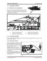
Page 101: ...tation 6 control lever lower control station 15 2 CONTROL SYSTEMS For STEYR MOTORS Marine Engines a mechanically operated control is provided However other control systems may be used too 15 2 1 Mechanical Control With mechanical control movement of the lever is transmitted through a steel cable in a plastic sleeve onto the engine and reversing gear This cable is called pressure and tension cable ...

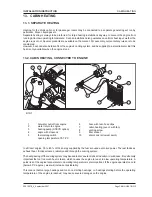
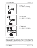
Page 102: ...erged with different qualities 15 2 3 Electronic Control With electronic control movement of the control lever are converted into electric signals In this case the microprocessor unit plays a central role It is attached as close as possible to the engine and controls via short tension and pressure cables the engine and the reversing gear 1 microprocessor unit 2 tension and pressure cable accelerat...

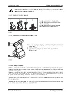
Page 103: ...sor units 3 tension and pressure cable accelerator 4 tension and pressure cable reversing gear 15 3 CONTROL LEVERS Speed and control levers should be of good quality to ensure a reliable control of the boat For hydraulic reversing gears we recommend the combined lever control for single and twin engines This control is designed in such a way that control of engine speed and hydraulically actuated ...

Page 104: ...be shortened or extended respectively connected piece by piece Cables for reversing gear and engine normally have different lengths These lengths are to be considered and or measured exactly when planning the cable run The cables must be laid unrestrictedly and only be clipped at the spots provided If necessary cables may be laid in cable protection pipes The speed cable must not be clipped closer...

Page 105: ...amechanicalshiftunit Manoeuvringandcontrol apparatus are installed twice Conversion of the control levers between the individual control stations may be done automatically if an omnibus implement is provided The speed cables of the two controls are connected to the actuator solenoid unit Automatic commutation of the connecting cables between the control stations one for every engine should be plac...

Page 106: ...RUCTION instrument panel with cable 7m instrument panel with cable 1 5 m extension cable 6 3 m 15 6 TWIN INSTRUMENT PANELS 15 6 1 Scheme for second instrument panel standard equipment optional equipment Y branch NOTE Oil pressure sender for twin installation must be changed ill 15 10 ...

Page 107: ...ION INSTALLATION INSTRUCTION standard equipment optional equipment 15 6 2 Scheme for instrument panel and SCC instrument panel with cable 7m SCC with cable 1 m Y branch extension cable 6 3 m NOTE Oil pressure sender for twin installation must be changed ill 15 11 ...

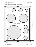
Page 108: ...CONTROL STATION Page CONTROL STATION 10 Z001007 0_4_September 2007 INSTALLATION INSTRUCTION ill 15 12 15 6 3 Cut out drawing for STANDARD Instrument Panel ...

Page 109: ...Z001007 0_4_September 2007 Page CONTROL STATION 11 CONTROL STATION INSTALLATION INSTRUCTION 15 6 4 Cut out drawing for SOLAS Instrument Panel 7 91 201mm 5 63 143 mm R 0 2 R 5 m m ill 15 13 ...

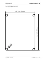
Page 110: ...CONTROL STATION Page CONTROL STATION 12 Z001007 0_4_September 2007 INSTALLATION INSTRUCTION 15 6 5 Cut out drawing for SCC inch 6 93 176 mm inch 5 63 143 mm 0 394 1 0 m m ...

Page 111: ...ALLATION INSTRUCTION 16 ELECTRICAL EQUIPMENT TABLE OF CONTENTS 16 1 GENERAL 3 16 2 BATTERIES 3 16 3 BATTERY CABLE LENGTHS AND CROSS SECTIONS 4 16 4 ADDITIONAL CURRENT UTILIZATION DEVICES 5 16 5 COMPUTATION OF CABLE CROSS SECTION FOR ADDITIONAL EQUIPMENT 6 16 6 CABLE CROSS SECTION 6 ...

Page 112: ...ELECTRICAL EQUIPMENT Page ELECTRICAL EQUIPMENT 2 Z001007 0_4_September 2007 INSTALLATION INSTRUCTION 16 ELECTRICAL EQUIPMENT NOTES ...

Page 113: ...on of the sea Provide easy access to the box for servicing the batteries as well as proper ventilation as the batteries generate small amounts of explosive gas Install main switches at the positive and negative side In case of one single switch install it easily accessible at the positive side Required capacity of main switches min 1000A short circuit current Attention Only bipolar systems may be ...

Page 114: ...e positive cable 3 0 m ground cable 2 0 m Total length 5 0 m cable cross section 70 mm For ground connection determine corresponding cross sections as per chart In general take care that battery cable lengths are kept as short as possible starter engine 3 kW 12 Volt battery size 110 AH length in m 0 0 3 0 3 1 4 5 4 6 5 5 cable cross section in mm 50 70 95 AWG 0 00 0000 For 6 cyl engines only start...

Page 115: ... all these components to guarantee sufficient capacity of the dynamos Example When using a 50A dynamo you may connect current utilization devices consuming all together 50A simultaneously In case of a too small capacity of the dynamo a larger or an additional dynamo may be installed Since the starting quality of the battery must be guaranteed max 90 45A of the rated capacity may be consumed simult...

Page 116: ...equired cabel length is 8 meters since cable length back and forth is to considered In the table a straight line is drawn from 8 in the length m column sloping downwards to 300 in the power column This straight line crosses the cross sectional column at 4 5 Therefore a cable with a cross section of 4 5 mm min is to be used This value is rounded up to the next cable size available length in m lengt...

Page 117: ...VE SARO 9 STERN DRIVE VOLVO 11 STERN DRIVE VOLVO DP 290 13 STERN DRIVE 15 STERN DRIVE BRAVO 17 JET DRIVE CASTOLDI 19 JETDRIVE CASTOLDI 21 JETDRIVE CASTOLDI 23 FRONT VIEW 25 BOBTAIL 27 DOWN ANGLE 29 STRAIGTH SHAFT 31 V DRIVE 33 JET DRIVE CASTOLDI 35 JET DRIVE CASTOLDI 37 STERN DRIVE MERCURY BRAVO II III 39 STERN DRIVE VOLVO DP 290 41 4 Cyl Marine Engine 6 Cyl Marine Engine ...

Page 118: ...TES Page DRILL TEMPLATES 2 Z001007 0_4_September 2007 INSTALLATION INSTRUCTION 17 DRILL TEMPLATES TABLE OF CONTENTS STERN DRIVE VOLVO DP 290 ZF 45 STERN DRIVE SX DRIVE OMC 47 TUNNELDRIVE SARO 49 6 Cyl Marine Engine ...

Page 119: ...TES 3 DRILL TEMPLATES INSTALLATION INSTRUCTION Drill templates scale approx 1 10 Front view without hydraulic pump with hydraulic pump 759 20 241 230 337 4 684 485 230 62 8 286 286 20 241 230 337 4 684 485 759 230 62 8 286 286 4 Cyl Marine Engine ...

Page 120: ...DRILL TEMPLATES Page DRILL TEMPLATES 4 Z001007 0_4_September 2007 INSTALLATION INSTRUCTION THIS PAGE IS INTENTIONALLY BLANK ...

Page 121: ..._September 2007 Page DRILL TEMPLATES 5 DRILL TEMPLATES INSTALLATION INSTRUCTION Drill templates scale approx 1 10 Bobtail without coupling 140 286 286 684 550 520 ø 14 62 8 31 702 847 24 20 759 4 Cyl Marine Engine ...

Page 122: ...DRILL TEMPLATES Page DRILL TEMPLATES 6 Z001007 0_4_September 2007 INSTALLATION INSTRUCTION THIS PAGE IS INTENTIONALLY BLANK ...

Page 123: ...LL TEMPLATES 7 DRILL TEMPLATES INSTALLATION INSTRUCTION Drill templates scale approx 1 10 Inboard with ZF 45A marine gear Down angle 8 286 286 684 650 621 140 ø 14 315 62 8 109 702 847 24 26 759 70 158 1007 77 125 930 4 Cyl Marine Engine ...

Page 124: ...DRILL TEMPLATES Page DRILL TEMPLATES 8 Z001007 0_4_September 2007 INSTALLATION INSTRUCTION THIS PAGE IS INTENTIONALLY BLANK ...

Page 125: ... 2007 Page DRILL TEMPLATES 9 DRILL TEMPLATES INSTALLATION INSTRUCTION Drill templates scale approx 1 10 Tunnel Drive SARO 62 8 702 847 24 26 759 286 286 684 650 621 70 158 1007 77 140 ø 14 315 ca 90 110 4 Cyl Marine Engine ...

Page 126: ...DRILL TEMPLATES Page DRILL TEMPLATES 10 Z001007 0_4_September 2007 INSTALLATION INSTRUCTION THIS PAGE IS INTENTIONALLY BLANK ...

Page 127: ... DRILL TEMPLATES 11 DRILL TEMPLATES INSTALLATION INSTRUCTION Drill templates scale approx 1 10 Stern Drive VOLVO DP 290 Hydraulic Exhaust type R4 R6 V8 62 8 593 847 24 759 286 286 684 581 551 109 114 702 140 ø 14 4 Cyl Marine Engine ...

Page 128: ...DRILL TEMPLATES Page DRILL TEMPLATES 12 Z001007 0_4_September 2007 INSTALLATION INSTRUCTION THIS PAGE IS INTENTIONALLY BLANK ...

Page 129: ... Page DRILL TEMPLATES 13 DRILL TEMPLATES INSTALLATION INSTRUCTION Drill templates scale approx 1 10 Stern Drive VOLVO DP 290 62 8 593 847 24 759 286 286 684 581 551 109 114 702 140 ø 14 Exhaust type R4 R6 V8 4 Cyl Marine Engine ...

Page 130: ...DRILL TEMPLATES Page DRILL TEMPLATES 14 Z001007 0_4_September 2007 INSTALLATION INSTRUCTION THIS PAGE IS INTENTIONALLY BLANK ...

Page 131: ...r 2007 Page DRILL TEMPLATES 15 DRILL TEMPLATES INSTALLATION INSTRUCTION Drill templates scale approx 1 10 SX Stern Drive 62 8 847 24 759 286 286 684 581 551 140 ø 14 593 758 292 6 89 18 8 11 128 114 37 4 Cyl Marine Engine ...

Page 132: ...DRILL TEMPLATES Page DRILL TEMPLATES 16 Z001007 0_4_September 2007 INSTALLATION INSTRUCTION THIS PAGE IS INTENTIONALLY BLANK ...

Page 133: ...2007 Page DRILL TEMPLATES 17 DRILL TEMPLATES INSTALLATION INSTRUCTION Drill templates scale approx 1 10 MERCURY ALPHA BRAVO II III 114 62 8 847 24 20 5 759 286 286 684 583 553 140 ø 14 240 593 111 732 28 4 Cyl Marine Engine ...

Page 134: ...DRILL TEMPLATES Page DRILL TEMPLATES 18 Z001007 0_4_September 2007 INSTALLATION INSTRUCTION THIS PAGE IS INTENTIONALLY BLANK ...

Page 135: ...2007 Page DRILL TEMPLATES 19 DRILL TEMPLATES INSTALLATION INSTRUCTION Drill templates scale approx 1 10 Jet Drive CASTOLDI 62 8 31 702 847 24 20 759 140 286 286 684 550 520 ø 14 ø 108 6 x M12 103 212 1017 4 Cyl Marine Engine ...

Page 136: ...DRILL TEMPLATES Page DRILL TEMPLATES 20 Z001007 0_4_September 2007 INSTALLATION INSTRUCTION THIS PAGE IS INTENTIONALLY BLANK ...

Page 137: ...007 Page DRILL TEMPLATES 21 DRILL TEMPLATES INSTALLATION INSTRUCTION Drill templates scale approx 1 10 Jet Drive CASTOLDI 62 8 31 702 847 24 20 759 140 286 286 684 550 520 ø 14 ø 101 5 8 x M10 103 405 1210 4 Cyl Marine Engine ...

Page 138: ...DRILL TEMPLATES Page DRILL TEMPLATES 22 Z001007 0_4_September 2007 INSTALLATION INSTRUCTION THIS PAGE IS INTENTIONALLY BLANK ...

Page 139: ...mber 2007 Page DRILL TEMPLATES 23 DRILL TEMPLATES INSTALLATION INSTRUCTION Drill templates scale approx 1 10 Jet Drive CASTOLDI 05 62 8 31 702 847 24 20 759 1210 11 5 780 140 286 286 684 550 520 ø 14 4 Cyl Marine Engine ...

Page 140: ...DRILL TEMPLATES Page DRILL TEMPLATES 24 Z001007 0_4_September 2007 INSTALLATION INSTRUCTION THIS PAGE IS INTENTIONALLY BLANK ...

Page 141: ...PLATES 25 DRILL TEMPLATES INSTALLATION INSTRUCTION Drill templates scale approx 1 10 Front view with hydraulic pump without hydraulic pump 778 526 252 669 332 337 55 8 286 286 24 55 8 778 526 252 669 332 337 24 55 8 286 286 6 Cyl Marine Engine ...

Page 142: ...DRILL TEMPLATES Page DRILL TEMPLATES 26 Z001007 0_4_September 2007 INSTALLATION INSTRUCTION THIS PAGE IS INTENTIONALLY BLANK ...

Page 143: ..._4_September 2007 Page DRILL TEMPLATES 27 DRILL TEMPLATES INSTALLATION INSTRUCTION Drill templates scale approx 1 10 Bobtail 55 8 1033 778 ca 137 196 895 31 24 20 286 568 286 296 669 140 ø 14 6 Cyl Marine Engine ...

Page 144: ...DRILL TEMPLATES Page DRILL TEMPLATES 28 Z001007 0_4_September 2007 INSTALLATION INSTRUCTION THIS PAGE IS INTENTIONALLY BLANK ...

Page 145: ...LATES 29 DRILL TEMPLATES INSTALLATION INSTRUCTION Drill templates scale approx 1 10 Inboard with ZF 63A marine gear Down Angle 8 286 711 286 296 669 140 ø 14 355 55 8 1033 778 ca 137 196 895 24 1156 109 112 153 57 20 144 265 6 Cyl Marine Engine ...

Page 146: ...DRILL TEMPLATES Page DRILL TEMPLATES 30 Z001007 0_4_September 2007 INSTALLATION INSTRUCTION THIS PAGE IS INTENTIONALLY BLANK ...

Page 147: ...LATES 31 DRILL TEMPLATES INSTALLATION INSTRUCTION Drill templates scale approx 1 10 Inboard with ZF 63 marine gear Straight Shaft 55 8 1033 778 ca 137 109 196 1217 24 895 112 126 5 161 49 273 286 711 286 296 669 355 140 ø 14 6 Cyl Marine Engine ...

Page 148: ...DRILL TEMPLATES Page DRILL TEMPLATES 32 Z001007 0_4_September 2007 INSTALLATION INSTRUCTION THIS PAGE IS INTENTIONALLY BLANK ...

Page 149: ... TEMPLATES 33 DRILL TEMPLATES INSTALLATION INSTRUCTION Drill templates scale approx 1 10 Inboard with ZF IV marine gear V Drive 12 140 ø 14 286 781 286 55 8 1033 778 ca 137 109 296 196 1221 669 24 182 219 2 355 326 895 6 Cyl Marine Engine ...

Page 150: ...DRILL TEMPLATES Page DRILL TEMPLATES 34 Z001007 0_4_September 2007 INSTALLATION INSTRUCTION THIS PAGE IS INTENTIONALLY BLANK ...

Page 151: ...07 Page DRILL TEMPLATES 35 DRILL TEMPLATES INSTALLATION INSTRUCTION Drill templates scale approx 1 10 Jet Drive CASTOLDI 286 568 286 296 669 140 ø 14 55 8 1033 778 ca 137 31 196 895 24 ø 108 6 x M12 212 20 6 Cyl Marine Engine ...

Page 152: ...DRILL TEMPLATES Page DRILL TEMPLATES 36 Z001007 0_4_September 2007 INSTALLATION INSTRUCTION THIS PAGE IS INTENTIONALLY BLANK ...

Page 153: ... Page DRILL TEMPLATES 37 DRILL TEMPLATES INSTALLATION INSTRUCTION Drill templates scale approx 1 10 Jet Drive CASTOLDI 20 ø 101 5 8 x M10 405 55 8 1033 778 ca 137 31 196 895 24 24 286 568 286 296 669 140 ø 14 6 Cyl Marine Engine ...

Page 154: ...DRILL TEMPLATES Page DRILL TEMPLATES 38 Z001007 0_4_September 2007 INSTALLATION INSTRUCTION THIS PAGE IS INTENTIONALLY BLANK ...

Page 155: ...e DRILL TEMPLATES 39 DRILL TEMPLATES INSTALLATION INSTRUCTION Drill templates scale approx 1 10 Stern Drive MERCURY BRAVO II III 286 602 286 296 669 240 140 ø 14 111 114 55 8 1033 778 ca 137 196 903 24 28 20 5 24 6 Cyl Marine Engine ...

Page 156: ...DRILL TEMPLATES Page DRILL TEMPLATES 40 Z001007 0_4_September 2007 INSTALLATION INSTRUCTION THIS PAGE IS INTENTIONALLY BLANK ...

Page 157: ...DRILL TEMPLATES 41 DRILL TEMPLATES INSTALLATION INSTRUCTION Drill templates scale approx 1 10 Stern Drive VOLVO DP 290 286 610 286 296 669 140 ø 14 20 5 111 55 8 1033 778 ca 137 196 114 911 24 Exhaust type R6 R4 V8 6 Cyl Marine Engine ...

Page 158: ...DRILL TEMPLATES Page DRILL TEMPLATES 42 Z001007 0_4_September 2007 INSTALLATION INSTRUCTION THIS PAGE IS INTENTIONALLY BLANK ...

Page 159: ...2007 Page DRILL TEMPLATES 43 DRILL TEMPLATES INSTALLATION INSTRUCTION Drill templates scale approx 1 10 Stern Drive STERN POWER S1000 286 599 286 296 669 140 ø 14 20 5 55 8 778 ca 137 196 305 895 1205 24 6 Cyl Marine Engine ...

Page 160: ...DRILL TEMPLATES Page DRILL TEMPLATES 44 Z001007 0_4_September 2007 INSTALLATION INSTRUCTION THIS PAGE IS INTENTIONALLY BLANK ...

Page 161: ... TEMPLATES 45 DRILL TEMPLATES INSTALLATION INSTRUCTION Drill templates scale approx 1 10 Stern Drive VOLVO DP 290 Hydraulic 286 610 286 296 669 140 ø 14 20 5 111 55 8 1033 778 ca 137 196 114 906 24 Exhaust type R4 R6 V8 6 Cyl Marine Engine ...

Page 162: ...DRILL TEMPLATES Page DRILL TEMPLATES 46 Z001007 0_4_September 2007 INSTALLATION INSTRUCTION THIS PAGE IS INTENTIONALLY BLANK ...

Page 163: ...LL TEMPLATES 47 DRILL TEMPLATES INSTALLATION INSTRUCTION Drill templates scale approx 1 10 VOLVO SX Drive King Cobra Drive 286 610 4 286 296 669 292 6 89 140 ø 14 55 8 1033 778 ca 137 196 786 18 8 11 128 114 37 914 24 6 Cyl Marine Engine ...

Page 164: ...DRILL TEMPLATES Page DRILL TEMPLATES 48 Z001007 0_4_September 2007 INSTALLATION INSTRUCTION THIS PAGE IS INTENTIONALLY BLANK ...

Page 165: ...9 DRILL TEMPLATES INSTALLATION INSTRUCTION Drill templates scale approx 1 10 Tunnel Drive SARO STEYR ENGINE STP 320 ZF 63 A 8 286 711 286 296 669 140 ø 14 355 ca 90 110 55 8 1033 778 ca 137 109 196 895 112 153 57 144 1156 265 20 24 6 Cyl Marine Engine ...

Page 166: ...DRILL TEMPLATES Page DRILL TEMPLATES 50 Z001007 0_4_September 2007 INSTALLATION INSTRUCTION THIS PAGE IS INTENTIONALLY BLANK ...

Page 167: ...001007 0_4_September 2007 Page APPENDIX 1 APPENDIX INSTALLATION INSTRUCTION 18 APPENDIX TABLE OF CONTENTS PROPELLER CALCULATION FORM INSTALLATION AND PRE DELIVERY INSPECTION LOG OWNER IDENDIFICATION CARD ...

Page 168: ...APPENDIX Page APPENDIX 2 Z001007 0_4_September 2007 INSTALLATION INSTRUCTION 18 APPENDIX NOTES ...

Page 169: ...m transom LCG m Over all width of boat B max m Width of boat at water line Bc max m Width of boat at transom Bct m Over all height of boat H m V angle boat centre ß at V angle at transom ß t Engine model Propeller Data Diameter inch Pitch inch Number of blades Sense of rotation Material Gear Gear type Reduction of speed 1 Shaft diameter mm Slope of shaft Cone 1 Costs contribution to propeller comp...

Page 170: ...APPENDIX Page APPENDIX 4 Z001007 0_4_September 2007 INSTALLATION INSTRUCTION THIS PAGE IS INTENTIONALLY BLANK ...

Page 171: ...ne coolant temperature C Exhaust gas raw water temperature C Fuel rate of flow at idle run measured from return line l min Idle speed rpm Name of datalog Model No Boat length m Boat weight kg Driving system Propeller Level of operating fluids motor oil gear oil hydraulic oil cooling agent checked yes Leakage oil fuel coolant checked Instruments adjusted Type of secondary drive if available Type of...

Page 172: ...APPENDIX Page APPENDIX 6 Z001007 0_4_September 2007 INSTALLATION INSTRUCTION THIS PAGE IS INTENTIONALLY BLANK ...

Page 173: ...Z001007 0_4_September 2007 Page APPENDIX 7 APPENDIX INSTALLATION INSTRUCTION ...

Page 174: ...APPENDIX Page APPENDIX 8 Z001007 0_4_September 2007 INSTALLATION INSTRUCTION THIS PAGE IS INTENTIONALLY BLANK ...

Reviews: