


Z001007/0_4_September 2007
Page ELECTRICAL EQUIPMENT-3
ELECTRICAL EQUIPMENT
INSTALLATION INSTRUCTION
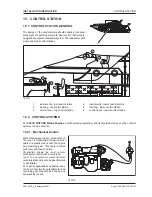
16. ELECTRICAL EQUIPMENT
16. 1. GENERAL
Cable laying is to be planned and carried out precisely and carefully. Cables must be approved for marine
operation. Pull the cables through appropriate protective sleeves to be fixed properly. Make sure that cables are
not too close to hot parts of the engine. Cables must not be exposed to mechanical wear and mechanical
abrasion. If necessary, pull the cables through protection tubes.
Attention:
Never fix a cable in such a way that it could lay in bilge water.
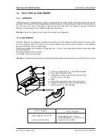
16. 2. BATTERIES
Install the batteries in a battery box situated low in the boat to avoid leaking of battery acid due to motion of the
sea. Provide easy access to the box for servicing the batteries, as well as proper ventilation, as the batteries
generate small amounts of explosive gas.
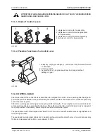
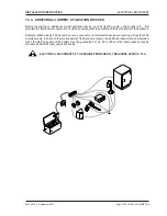
Install main switches at the positive and negative side. In case of one single switch, install it easily accessible
at the positive side.
Required capacity of main switches:
min. 1000A (short-circuit current)
Attention:
Only bipolar systems may be installed otherwise galvanic streams may occur which cause corrosion.
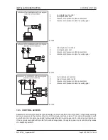
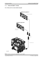
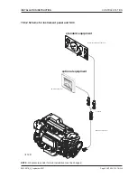
1 air tube, at least 25mm (1"), conducted outwards
2 cover, same material as box
3 clamping bar, which fixes the battery by securing
the nuts (L-iron or flat bar)
4 studs
5 box made of steel plate (min. 3mm) acid-proof
6 clamps with tightening screws (use pole grease)
7 rubber sleeves for cable passage
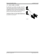
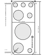
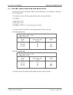
rated capacity: 12V / 92 Ah
cold test current: 450 A
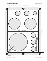
rated capacity: 12V / 115 Ah
for 24V installation: 2 x 12V/ 115 AH
cold test current: 650 A
6 Cyl. Engine
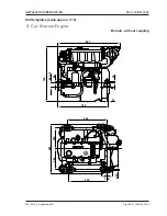
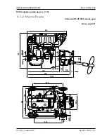
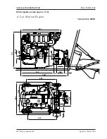
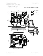
4 Cyl. Engine