


CONTROL STATION
Page CONTROL STATION-6
Z001007/0_4_September 2007
INSTALLATION INSTRUCTION
ATTENTION: WHEN ENGAGING REVERSING GEARS OR CLUTCHES, THE ENGINE SPEED
NEVER SHOULD EXCEED 800 RPM.
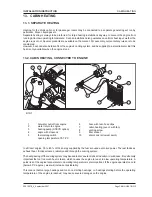
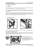
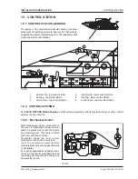
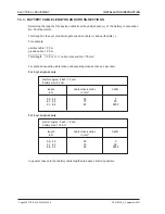
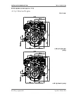
15.3.1. Kinds of Control Levers
1 single-lever control, for top asembly
2 single-lever control for twin-engine plant,
for top assembly
3 single-lever control for lateral assembly
4 twin-lever control for top assembly
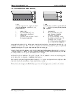
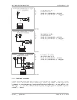
15.3.2. Possible Functions of a Control Lever
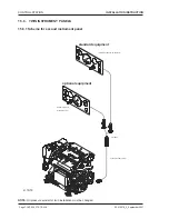
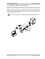
15.4. CONTROL CABLE
Cables provided for the control devices described are designed for function in two operating directions (push-
pull function) and available in many different lengths. Cables should not be shortened or extended respectively
connected piece by piece.
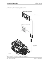
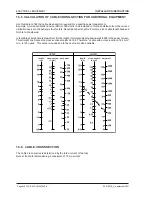
Cables for reversing gear and engine normally have different lengths. These lengths are to be considered and/
or measured exactly when planning the cable run. The cables must be laid unrestrictedly and only be clipped at
the spots provided. If necessary, cables may be laid in cable-protection pipes.
The speed cable must not be clipped closer than 0,9 m to the control, since this cable moves a slightly back and
forth during operation.
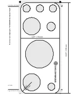
The speed and reversing gear cables are to be laid in as few as possible smooth curves, to avoid unnecessary
friction and clearance losses. Min. curve radius is 150mm.
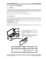
ill. 15/7
ill. 15/8
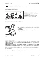
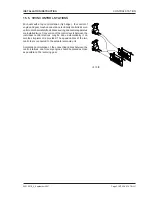
1 safety key: only by pressing key 1, control lever may be moved forward
or backward.
2 trimming switch
3 by pressing key 3, engine speed may be changed without
putting in a gear