


Z001007/0_4_September 2007
Page ENGINE INSTALLATION-7
ENGINE INSTALLATION
INSTALLATION INSTRUCTION
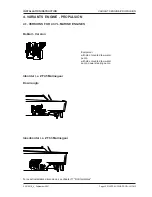
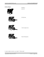
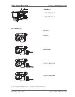
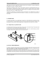
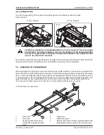
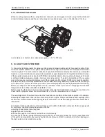
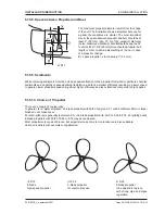
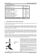
5.6. LIFTING EYES
To permit an easy lifting of the engine, strong lifting eyes are provided bow- and stern-sided.
See ill. 5/6 u.5/7.
ATTENTION: NEVER PLACE THE ENGINE DIRECTLY ONTO THE FLOOR. THE OIL PAN AND
OTHER PARTS COULD BE DAMAGED. JACK UP THE ENGINE ON THE ENGINE BEARERS
SO THAT ITS LOWER PART IS TRAILING, OR KEEP THE ENGINE IN THE TRANSPORT BOX
UNTIL IT IS LIFTED INTO THE BOAT.
Do not lift the engine from any single lifting point, damage to the engine or personnel injury could accrue. When
having to tilt the engines for installation use an adjustable load leveler to aid in installation.
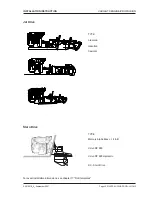
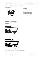
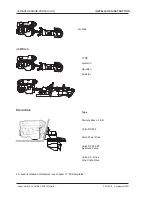
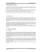
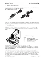
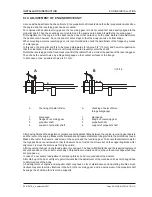
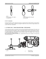
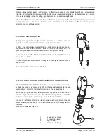
5.7. CHECKING OF ENGINE BASE
When preparing the engine base, make sure that the upper contact surfaces of the bearers are parallel to the
centre line of the propeller shafts and are not swung. For assistance during assembly and checking of the engine
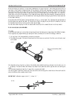
base, a short traversing slide with the same diameter as the propeller shaft may be used stern-sided; see ill. 5/
8. Through a bore ( 1/12" / 2mm diameter) in the slide a 1/12" (2 mm) copper wire is strained to a holder. Then
adjust the holder in such a way that the wire is in the centre of the front end of the propeller shaft sleeve.
Then measure the base bearers and check their correct height and that they are not swung.
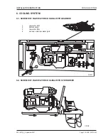
1
steel rulers
2
stem tube
3
traversing slide (dimensions
correspond to respective shaft
size)
4
copper wire
5
holder with chuck
6
distance engine base surface - propeller shaft centre
(depending on type of engine and reversing gear)
ill. 5/6
ill. 5/7
1
1
ill. 5/8 checking of engine base
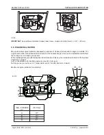
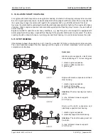
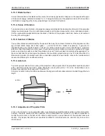
4 Cyl. Engine
6 Cyl. Engine