
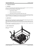


AIR INTAKE AND VENTILATION
Page AIR INTAKE AND VENTILATION-6
Z001007/0_4_September 2007
INSTALLATION INSTRUCTION
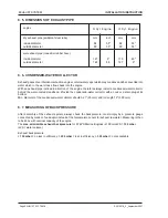
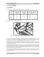
9. 9. CHOICE OF BLAST
The blast is to be provided for the following air volume flow:
air volume flow (m³/min) = 0,07 x engine power in kW
For example:
256 marine
0,07 x 184 = approx. 17 yd³/min (13 m³/min)
164 marine
0,07 x 120 = approx. 11,8 yd³/min (9 m³/min)
Total pressure rise by the blast should be 3/8" wc (10 mm WS) (100 Pa).
Based on these two values, air volume flow and total pressure rise, the blast may be chosen.
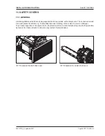
9. 10. FUNCTION OF AIR INLETS
Satisfactory function of air inlets and air outlets must also be guaranteed with bad weather conditions. They
should have water guards, and normally sound insulation too.
Distances between air inlets and air outlets should be as long as possible.
Provide for a good air flow.
Attention:
If the distance between inlet and outlet is too short, the air may circulate which results in a bad
ventilation effect.
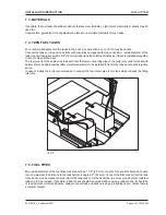
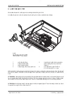
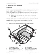
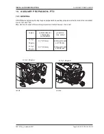
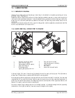
9. 11. POSITION OF AIR PIPES
Lay the pipes for air supply of the engine
up to the air filter's side, but with a lateral distance of 8" - 12"
(20 - 30 cm), to absolutely avoid any entering of water into the engine.
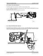
Air inlets and air outlets must never be installed in the stern transom.
In this area the air is mixed with water
and exhaust gases and, therefore, never may be conducted into the boat.
For Diesel engines, the air supply pipes should end at low level in the engine compartment, but not too low to
cause a fluidity stop (brackish water) which chokes the air supply.
Exhaust air pipes are to be provided diagonally on the opposite side of the engine.