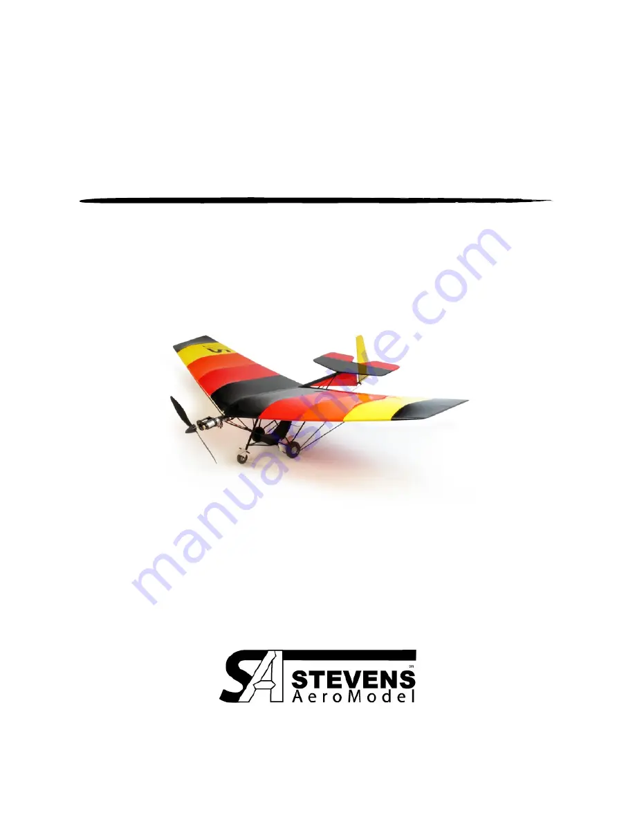
eHopper
By Stevens AeroModel
Span 33.5 inches | Length 21.5 inches | Wing Area 235 inches
2
| Flying Weight 4.5 - 5.5 oz.
Version 02/02//2010
TM
© 2009 Stevens AeroModel all rights reserved.
Page 1 of 36
Page 1: ...eHopper By Stevens AeroModel Span 33 5 inches Length 21 5 inches Wing Area 235 inches2 Flying Weight 4 5 5 5 oz Version 02 02 2010 eHopperTM 2009 Stevens AeroModel all rights reserved Page 1 of 36...
Page 2: ...t prepared to accept the liability associated with the use of this product the buyer is advised to return this kit immediately in new and unused condition to the place of purchase THIS PRODUCT IS NOT...
Page 3: ...levator Joiner 2 Micro II E Z Links for 0 045 in wire DUB920 BULK27805 4 Micro Control Horn Single Post DUB848 BULK26305 6 Micro E Z Links for 0 032 in wire DUB849 BULK26310 6 Mini Rubber Bands Black...
Page 4: ...Brushed Power System Recommended GWS IPS S2 motor GW IPS DX2BB 2XCS Castle Creations Pixie 7P ESC GWS 7x6 Slow Fly Propellor 7 4V Hyperion 120mAh CX G3 LiPo Brushless Power System E Flite Park 250 EF...
Page 5: ...in the assembly process Protecting your worktable Use the poly tube that this kit was shipped in as a non stick barrier between your worktable and the product assembly Bonding the assembly As this pro...
Page 6: ...l bits to align Start with left wing Fit spar S1 to center rib assembly Ensure that spar seats snug against R1 Tack glue with thin CA With rib spar assembly flat on the table fit leading edge W1 to R1...
Page 7: ...S2 to ribs Square wing on table and bond NOTE tip of spar rests ON TOP of wing tip Fit Leading Edge W4 and bond to W1 and ribs Arrow on leading edge indicates position at wing center Cut 1 8 in carbon...
Page 8: ...ill to form hole for wing mount bolt Install 4 40 blind nut through hole from the top of the rib Nut may be recessed slightly to facilitate smooth covering Secure blind nut with thin CA around edges o...
Page 9: ...eave approximately 1 32 in gap between surfaces Apply 3 4 in clear tape over gap to form elevator hinge Ensure there is adequate down travel If not remove tape increase gap between surfaces slightly a...
Page 10: ...TE or AeroFILM Open slots for hinges with hobby knife or razor blade Fit ply hinge pieces R5 in slots Do not glue at this time Remove covering from control horn mount at base of rudder Fit control hor...
Page 11: ...er with medium CA Remove wire Assemble vertical stabilizer per plan Lightly sand vertical sub fin rounding lower edge Leave upper edge and trailing edge square Cover vertical stabilizer Remove coverin...
Page 12: ...medium CA Using guide slots in F1b drill 1 8 in hole for wing mount Seal boom with at least 2 coats of Deft lacquer or similar clear lacquer spray If desired paint boom black at this time with Design...
Page 13: ...ut assembly with two coats of Deft DO NOT SKIP THIS STEP If not sealed the ply struts may absorb moisture and warp Paint strut assembly black and repeat sealing process Repeat previous steps to assemb...
Page 14: ...6400 Instruction Given For JR S185 Micro Servos Fit seat side S1a S1b if building for AR6400 to seat bottom S3 tack glue with thin CA Fit the other side S1a to seat bottom Tack glue in place Fit seat...
Page 15: ...eat struts F7 to side and front as shown Ensure struts are in the same plane as the base of the seat Bond with medium CA Seal seat assembly with two light coats of Deft and paint desired color For Spe...
Page 16: ...with the fuselage boom Fit two ply sides F8b to ply wheel fork F8a and tack with thin CA Fit fender front F8c to fork side assembly Bond entire assembly with medium CA Seal strut nose wheel assembly w...
Page 17: ...o length indicated on landing gear plan Do not bend other end at this point Cut two lengths of 1 16 in heat shrink tubing 1 3 8 in long to make axle spacers Install axle and seat in this order Slide a...
Page 18: ...bly Bond axle to hubs with medium CA Ensure bends at axle ends point down as indicated on landing gear plan Do not bond seat to axle at this time Shrink axle spacers using a fine tip soldering iron in...
Page 19: ...l joints with medium CA Fit vertical stabilizer to slot on bottom of fuselage boom Ensure stabilizer is aligned with the vertical centerline of fuselage and bond with Medium CA Using a 0 025 drill ope...
Page 20: ...ne of vertical stabilizer Bond hinge tab at vertical fin with medium CA Hinge pin may be left to float free or may be secure by CAREFULLY placing a drop of medium CA at top Ensure CA does not bind in...
Page 21: ...and horizontal stabilizers remain perpendicular to each other Bond with medium CA Fuel Tank Assemble fuel tank by stacking parts in this order bottom to top five T1 s one top T2 fuel cap body T3 fuel...
Page 22: ...s Strut Assebly Strut Wire Fittings Refer to Strut Assembly on plan Using 1 32 wire make a 90 degree bend 3 16 in from one end Trim wire to 1 in length Repeat to make four fittings Using 1 32 in wire...
Page 23: ...t carbon tube DO NOT GLUE Tape assembly to drawing on plan Insert long end of bent wires into tubes Carefully check finished length of struts Adjust tubes and wires as necessary Tack glue with thin CA...
Page 24: ...ound off point and trim stem to 1 8 in Drill a 1 32 in hole in each fitting as shown Open holes for fittings in wing using a fine point soldering iron Insert nylon fittings into holes in wing Do not g...
Page 25: ...rut end Bond fitting with medium CA Repeat process with opposite wing Remove wing and struts when finished Tail Rigging Optional Cut 1 16 dia x 1 4 in aluminum tube in half to form rigging crimps Plen...
Page 26: ...other end of strut as before Note Do not pull tail rigging too tight as this will pull the tail surfaces out of alignment Rig seat to fuselage boom in the same manner Pass wire over boom and pinch wi...
Page 27: ...ward struts as shown Note We recommend removing the connectors from the motor and speed control reducing the length of wire and directly soldering both components together Conventional Gear JR S185 Se...
Page 28: ...ntrol horn as shown for the rudder servo Cut two 18 in lengths of rigging wire and attach to control horn in the same manner as done previously with the rigging wires Electronically center rudder serv...
Page 29: ...1 32 in wire make a 90 degree bend 1 8 from one end Trim fitting to 1 in Make two pushrod fittings Join fittings to pushrod with a 1 2 in length of 1 16 in heat shrink tube Shrink tube using a fine ti...
Page 30: ...to a 3 pin connector available from StevensAero Configure color coded wires as shown Remove connector from speed control Trim wires for a finished length of 11 in and solder on extension Ensure colore...
Page 31: ...control horn and servo Use outer most hole at control horn Join fittings to pushrod with a 1 2 in length of heat shrink tube Shrink tube using a fine tip soldering iron Pushrod connects to the right...
Page 32: ...ugh right side of rudder horn Center rudder and snug wire Do not crimp yet Attach second wire to left side of control horn Snug wire but do not crimp Attach control wire to supplied connector SIGSH445...
Page 33: ...der to full left position reliably Do not over tension rubber band as this may stress the servo When satisfied that rubber band has proper tension crimp wire to final length Mount 7 4V two cell 120mAh...
Page 34: ...g you ve written having a second fresh set of eyes to inspect your final product is often helpful at avoiding disaster While not an exhaustive pre flight check these are some of the major items that y...
Page 35: ...d cut power just before rounding out for landing eHopper will float in ground effect briefly and settle to the ground on the mains DO NOT ATTEMPT 3 POINT LANDINGS Just like the full size craft The eHo...