background image

//

 ZS 80 ... KST Extreme

st

eut

e T

echnol

ogies GmbH & Co. K

G, 

Brück

ens

tr

aße 91, 32584 Löhne, Germany

, www

.s

teut

e.c

om

3 / 20

Montage- und Anschlussanleitung / Seilzug-Notschalter

Mounting and wiring instructions / Emergency pull-wire switch

Instructions de montage et de câblage / Arrêt d’urgence à commande par câble

Istruzioni di montaggio e collegamento / Interruttore di emergenza a fune

Instruções de montagem e instalação / Chave de emergência acionada por cabo

Инструкция по монтажу и подключению / Аварийный тросовый выключатель

Installation, mounting, dismantling

=

DANGER

Live parts. 

Electric shock hazard! 

Connecting and 

disconnecting only to be performed by qualified and 

authorised personnel. Connecting and disconnect-

ing only in zero potential state.

NOTICE

Untight if mounted at low temperatures. Mount 

carefully at low temperatures.

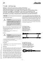
Before mounting the pull-wire, remove the red PVC sheath from the 

the pull-wire in the clamping range of the pull-wire! After fitting the 

wire, pull strongly on it several times, as the pull-wire and the wire 

thimble will deform. Subsequently, retense the wire using the DUPLEX 

wire clamp, eye-bolt or tensioner.

Application and operation

=

DANGER

Live parts. 

Electric shock hazard! 

Protective cover 

over contacts must be intact.

CAUTION

In case of overloaded contacts too high operation 

temperatures.


Risk of burns!


For short-circuit  

protection use appropriate fuse size (see  

technical data).

-  Use device only within the permitted electrical load limits (see  

technical data).

Mounting and set-up

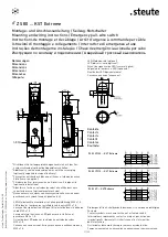
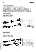
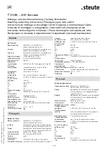
In order to function correctly, the emergency pull-wire switch must 

be set up in the middle position with a pretensioned pull wire. In this 

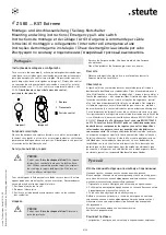
middle position the pointer position should correspond to Fig. 1. In the 

middle position with a pretensioned pull wire, the NC contacts, e.g.  

11-12, are closed and the NO contacts, e.g. 23-24, are open. 

The 

switch can only be released in this middle, pretensioned position.


       I  


Release


       0 


 Latching


            Middle position


         Fig. 1 

     Fig. 2

English

Switching function

When the wire is pulled, or if the wire breaks, the NC contacts, e.g. 

11-12, are opened and the NO contacts, e.g. 23-24, are closed and then 

locked in this position. The switch can only be released using the blue 

release lever.

Service, maintenance, repair

=

DANGER

Live parts. 

Electric shock hazard! 

Do not repair de-

fective or damaged devices.


Replace them.


Excep-

tion: Use steute’s original spare parts only to repair 

the device.


Do not rebuild or modify the device in 

any way.

With careful mounting as described above, only minor maintenance is 

necessary. We recommend a routine maintenance as follows:

1. Check pull-wire function.

2. Removal of dirt.

3. Check sealing of the cable or conduit connections.

Cleaning

=

DANGER

Live parts. 

Electric shock hazard! 

Observe degree 

of protection.

-  In case of damp cleaning: use water or mild, non-scratching, 

non-chafing cleaners.

- Do not use aggressive cleaners or solvents.

Disposal

- Observe national, local and legal regulations concerning disposal.

-  Recycle each material separately. 

N.B.

The electrical connection may only be carried out by authorised per-

sonnel. Any mounting position is possible. Reconstruction and alter-

ations at the switch - which might affect the safety function - are not 

allowed. The described products were developed in order to assume 

safety functions as part of an entire plant or machine. A complete 

safety system normally covers sensors, monitoring modules, indicator 

switches and concepts for safe disconnection. For the integration of 

the device in the entire system: strictly observe and respect the control 

category determined in the risk assessment. Therefore, a validation 

according to EN ISO 13849-2 or EN 62061 is necessary. 

Furthermore, 

the Performance Level according to EN ISO 13849-1 and SIL CL Level 

according to EN 62061 can be lower than the single level because of 

the combination of several safety components and other safety-relat-

ed devices, e.g. by serial connection of sensors. 

It is the responsibility 

of the manufacturer of a plant or machine to guarantee the correct 

general function. Subject to technical modifications. steute does not 

assume any liability for recommendations made or implied by this 

description. New claims for guarantee, warranty or liability cannot be 

derived from this document beyond the general terms and conditions 

of delivery.

Summary of Contents for ZS 80 KST Extreme Series

Page 1: ... eingesetzt an denen der Not Halt Schaltbefehl an beliebigen Punkten der Seilstrecke auszulö sen sein muss Ziehen am vorgespannten Zugseil oder Seilriss führen zur Ausführung der Schaltfunktion des Seilzug Notschalters und so mit zum Verrasten der Kontakte Die Rückstellung kann nur manuell durch Entriegelung mit dem Entriegelungsknopf erfolgen Installation Montage Demontage GEFAHR Spannungsführend...

Page 2: ... Spannungsführende Teile Stromschlaggefahr Beschädigte und defekte Geräte nicht reparieren sondern ersetzen Ausnahme Reparatur nur mit Original Ersatzteilen von steute durchführen Um bauten und Veränderungen am Gerät unterlassen Bei sorgfältiger Montage unter der Beachtung der oben beschriebe nen Hinweise ist nur eine geringe Wartung notwendig Wir empfehlen eine regelmäßige Wartung wie folgt 1 Prü...

Page 3: ...e g 11 12 are opened and the NO contacts e g 23 24 are closed and then locked in this position The switch can only be released using the blue release lever Service maintenance repair DANGER Live parts Electric shock hazard Do not repair de fective or damaged devices Replace them Excep tion Use steute s original spare parts only to repair the device Do not rebuild or modify the device in any way Wi...

Page 4: ...tre possible à n importe quel point du câble En tirant sur le câble de traction tendu ou une rupture du câble entraînent le déclenchement de la fonction de commutation de l arrêt d urgence à commande par câble et donc le verrouillage des contacts La réinitialisation ne peut être effectuée que manuellement en déverrouillant le bouton poussoir de déverrouillage Installation montage démontage DANGER ...

Page 5: ...tion Le déverrouillage n est possible que par le levier bleu de déverrouillage Maintenance entretien réparation DANGER Pièces sous tension Risque d électrocution Ne pas réparer les appareils endommagés ou défec tueux mais les remplacer Exception N utiliser que les pièces de rechange d origine steute pour effectuer des réparations S abstenir de faire des modifications ou changements de l appareil A...

Page 6: ...o ossia pretensionato tramite la fune in modo che venga raggiunta la posizione centrale In posizione centrale la posizione dell indicatore deve essere come riportato in Figura 1 In posizione centrale ossia con cavo pretensionato i contatti NC ad esempio 11 12 sono chiusi e i contatti NA ad esempio 23 24 sono aperti Lo sblocco è possibile soltanto in posizione centrale di pretensionamento I Sblocco...

Page 7: ...segurança ocupacio nal e prevenção de acidentes 3 Instalar e operar o dispositivo Seleção e instalação dos dispositivos e sua intregração no sistema de controle demanda conhecimento qualificado de todas as leis relevan tes assim como dos requerimentos norminativos do fabricante da máquina No caso de dúvidas prevalecerá a versão em alemão dessas instruções Escopo de entrega 1 dispositivo 1 instruçõ...

Page 8: ...escarte Separar materiais recicláveis Observações A ligação elétrica somente poderá ser executada por profissionais devidamente qualificados e credenciados O posicionamento de uso é livre Modificações e alterações no dispositivo as quais possa afetar a função de segurança não são permitidas Os produtos aqui descritos foram desenvolvidos para assumir as funções de segurança parcial e ou total de um...

Page 9: ...анным и специально уполномоченным персо налом Подключение и отсоединение от клемм только в обесточенном состоянии УВЕДOМЛЕНИЕ Негерметичность вследствие монтажа при низ ких температурах При низких температурах под ключать с особым вниманием Перед установкой троса удалить красную ПВХ оболочку в зоне за жима троса Так как при натяжении троса тросовые кауши дефор мируются трос после монтажа несколько...

Page 10: ... Электрические соединения должны осуществляться только специ ально уполномоченным персоналом Различные монтажные пози ции воз можны Переделки и изменения в устройстве которые могут ухудшить его функцию безопасности недопустимы Описанные здесь продукты были разработаны так чтобы в качестве составной части целой установки или машины взять на себя выполнение функций безопасности Полная система безопа...

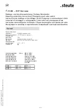
Page 11: ...mensions Dimensions Dimensioni Dimensões Габариты Nicht benutzte Leitungseinführungen zusätzlich mit der Ver schlussschraube optional beiliegend verschließen Additionally seal unused cable entries with the screw plug optionally supplied in scope of delivery Fermez les entrées de câbles non utilisées à l aide du bouchon fileté fourni en option Chiudere inoltre i pressacavi non utilizzati con il tap...

Page 12: ...onada por cabo Инструкция по монтажу и подключению Аварийный тросовый выключатель 6 6 0 5 10 15 20 25 30 35 40 45 50 ΔT K l m 120 100 80 60 40 20 0 Montage ohne Ausgleichsfeder Mounting without compensation spring Montage sans ressort de compensation Montaggio senza molla di compensazione Montagem sem mola de compensação Монтаж без компенсационной пружины 6 6 0 5 10 15 20 25 30 35 40 45 50 ΔT K l ...

Page 13: ...te ad occhiello M8 x 70 con dado 1170601 1189687 3 Morsetto 1033247 1033299 4 Redancia 3 mm 1033245 1172707 5 Molla di compensazione ZS 80 1187933 1230445 6 Fune di trazione 1 m 1032984 1033297 N Parte Número de item Aço ino xidável 1 Tensionador de cabo TS 65 1186621 2 Parafuso com olhal M8 x 70 com porca 1170601 1189687 3 Presilha 1033247 1033299 4 Olhal de proteção 3 mm 1033245 1172707 5 Mola d...

Page 14: ... fibreglass reinforced shockproof thermo plastic self extinguishing UL 94 V 0 Tightening torque cover screws 1 8 Nm Degree of protection IP67 to IEC EN 60529 Contact material silver Switching elements 2 NC 2 NO 3 NC 1 NO or 4 NC type Zb Switching system slow action positive break NC contacts A Connection 2 x 4 pole terminal block Cable cross section max 2 5 mm2 incl conductor ferrules Cable entry ...

Page 15: ... 5 5 EN ISO 13850 EN ISO 13849 1 Invólucro termoplástico reforçado com fibras de vidro resistente a impacto autoextintor UL 94 V 0 Tampa termoplástico reforçado com fibras de vidro resistente a impacto autoextintor UL 94 V 0 Torque de fixação parafusos da tampa 1 8 Nm Grau de proteção IP67 conforme IEC EN 60529 Contatos prata Elementos de comutação 2 NF 2 NA 3 NF 1 NA ou 4 NF tipo Zb Sistema de co...

Page 16: ...ia acionada por cabo Инструкция по монтажу и подключению Аварийный тросовый выключатель Защита от короткого замыкания 2 A gG gN предохранитель Механ долговечность 100 000 циклы коммутации Максимальная длина троса 100 м Опоры троса необходимы через каждые 5 м Признаки распознавание движения и обрыва троса Температура окру жающей среды 25 C 70 C Mаркировка Ô Русский Herstellungsdatum 1H4 KW 14 2022 ...

Page 17: ...bindliche Unterschrift Rechtsverbindliche Unterschrift Rechtsverbindliche Unterschrift Rechtsverbindliche Unterschrift Rechtsverbindliche Unterschrift Rechtsverbindliche Unterschrift Rechtsverbindliche Unterschrift Rechtsverbindliche Unterschrift Rechtsverbindliche Unterschrift Rechtsverbindliche Unterschrift Rechtsverbindliche Unterschrift Rechtsverbindliche Unterschrift Rechtsverbindliche Unters...

Page 18: ... above mentioned electrical equipment conforms to the named directive Relevante UK Richtlinie Relevant UK directive Angewandte harmonisierte Normen Applied harmonised designated standards Anmerkungen Comments Supply of Machinery Safety Regulations 2008 EN 60947 5 1 2017 EN 60947 5 5 1997 A1 2005 A11 2013 A2 2017 Weitere angewandte UK Richtlinien Additionally applied UK directives Harmonisierte Nor...

Page 19: ... nationale ga Arna iarraidh sin gheobhaidh tú na treoracha tionóil agus na treorach seo i do theanga féin hr Na zahtjev ćete dobiti ova uputstva za montažu i priključenje i na svom jeziku hu Egyeztetés után kérésére ezt a szerelési és csatlakoztatási leírást biztosítjuk az ön anyanyelvén is it Questa istruzione di collegamento e montaggio e inoltre dispo nibile nella vostra lingua su richiesta lt ...

Page 20: ...instructions Emergency pull wire switch Instructions de montage et de câblage Arrêt d urgence à commande par câble Istruzioni di montaggio e collegamento Interruttore di emergenza a fune Instruções de montagem e instalação Chave de emergência acionada por cabo Инструкция по монтажу и подключению Аварийный тросовый выключатель 01 26 0 0689 118 95 91 10 2021 141791 Index e 1000 wd ...

Reviews: