background image

8

FAUCET INSTALLATION

D28 DUAL POWER

Step 1 – Installing the faucet

1. Shut off the water supply 
2. Cut an adequate opening in the wall for the dimensions of the D28 base (where 

you want to install the spout), and the corrugated tube.
3. Install the D28 dual power base and its attachments through the opening that 

was cut in the wall.
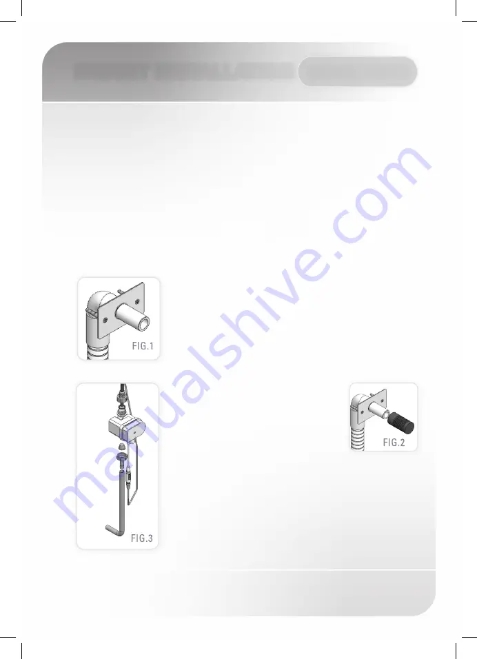
4. Mount the D28 base to the opening cut in the wall, and set 

it using the two small anchors provided. (See FIG. 1)

Important:

 The D28 base should be installed so that the 

outside surface of the finished wall falls between the 

minimum and maximum lines marked at the base. 
5. Assemble the temporary protective D28 base cover. 

(See FIG.2)

6. Make sure the corrugated tube will stay 

outside the wall when tiling.
7. Once the works on electricity, plumbing 

and tiles have been finished, insert the 

wall rosette through the D28 base. 
8. Cut the temporary D28 base cover.
9. Pull the four way connector out of the D28 base, and lead 

it along with the flexible tube, through the corrugated tube.
10. Connect the flexible tube to the solenoid valve body 

integrated in the dual power input box. (See FIG.3)
11. Fix the D28 spout by inserting the nipple into the D28 base 

and tighten the screw.

OPERATION:
This faucet features an IP67 dual power input box. The product can be operated 

with a 9V battery or a 9V transformer. In addition, when used with a transformer, 

the product contains an integrated battery back up, for normal use during power 

supply failures.

Summary of Contents for D28 352000

Page 1: ...1 WALL MOUNTED ELECTRONIC FAUCET FOR COLD OR PREMIXED WATER D28 SERIES D28 B D28 E D28 Dual Power B D28 Dual Power E D28 Box D28 Box E...

Page 2: ...NSTALLATION INFO 6 11 FAUCET INSTALLATION 12 14 SETTINGS ADJUSTMENT 15 BATTERY REPLACEMENT 16 MAINTENANCE Filters cleaning instructions Care and cleaning of chrome and special finishes 17 19 SPARE PAR...

Page 3: ...er Pressure Max Operating Water Pressure Sensor range Minimum sensor range Maximum sensor range Security time Hot water temperature 6x1 5V AA battery 9V Lithium battery 9V Lithium battery 9V transform...

Page 4: ...NTENTS D28 1 x Spout and attachments incl electronic unit M 4 x 4 set screw 1x D28 base 1 x Wall rosette B VERSIONS E VERSIONS IP67 Battery Box Transformer 1x Solenoid housing kit with inlet nipple an...

Page 5: ...attachments incl electronic unit M 4 x 4 set screw 1 x Wall rosette 1x D28 base 1 x Corrugated Tube 1x Dual power input box with inlet nipple and filter B VERSIONS E VERSIONS 1x Dual power input box...

Page 6: ...former 1 x Plastic box with concealed solenoid valve 1 x Temporary protective panel 1 x Spout and attachments incl electronic unit M 4 x 4 set screw 1x D28 base 1 x Wall rosette 1 x Panel with battery...

Page 7: ...the missing parts Preparation for installation Flush water supply lines thoroughly before installing the faucet Do not allow dirt Teflon tape or metal particles to enter the faucet Shut off water sup...

Page 8: ...ashbasin 5 Insert the anti rotation pin into the small hole if needed 6 Fix the base behind the wall with the hexagonal nut and the disk Step 2 Connecting the water supply 1 Fit the flexible pipe comi...

Page 9: ...r Plug the transformer into the electricity socket 3 After you have connected the power source Battery or Transformer wait 15 seconds in order to allow the system to set the ideal sensor range As an i...

Page 10: ...tive D28 base cover See FIG 2 6 Make sure the corrugated tube will stay outside the wall when tiling 7 Once the works on electricity plumbing and tiles have been finished insert the wall rosette throu...

Page 11: ...stem to set the ideal sensor range As an indication that the self adjusting has taken place a red light in the sensor eye will flash continuously The solenoid valve will open and close for 1 second as...

Page 12: ...t the D28 base 6 Assemble the corrugated tube between the D28 base and the box and lead the connectors through the D28 base and through the D28 box 6 Assemble the temporary protective cover panel to t...

Page 13: ...range As an indication that the self adjusting is taking place a red light in the sensor eye will flash continuously The solenoid valve will be opened and closed for 1 second as an indication that th...

Page 14: ...er to adjust the sensor with the remote control hold the remote control straight in front of the sensor in a distance of about 6 8 15 20cm Choose the function you want to adjust by pressing once on on...

Page 15: ...water flow will shut automatically To resume regular operation any obstruction must be removed Press the SEC button Wait until a quick flashing of the red light of the sensor eye is perceived Then pre...

Page 16: ...e the hygiene flush press the clock button Wait until a quick flashing of the red light of the sensor eye is perceived Then press to activate the hygiene flush or to deactivate it DELAY OUT TIME This...

Page 17: ...box carefully and remove the old battery Replace the used battery with a new 9V battery Lithium battery is recommended Close the box and re assemble the wall cover panel Important D28 was supplied wit...

Page 18: ...at the panel and remove it Turn off the regulating valve b Disassemble the solenoid valve by opening the nuts c Remove the filter and wash it under running water d Reassemble the filter e Reassemble...

Page 19: ...ST D28 Screws Kit Nano Sensor Solenoid BS Housing Kit Solenoid BS Housing Kit for USA Solenoid Valve Kit Diaphragm IP 67 Battery box Battery box 07210101 08004001 07231008 07231009 07230017 04500001 0...

Page 20: ...WER Seals and Screws Kit Nano Sensor Solenoid Housing Dual Power Kit Solenoid Housing Dual Power Kit USA Stern Interoperable LS9V12WC1 Dual Power Cover Kit Transformer 07210102 08004012 07231011 07231...

Page 21: ...IST D28 BOX Seals and Screws Kit Nano Sensor Solenoid Housing Kit Solenoid Housing Kit USA Solenoid Valve Kit Diaphragm Battery box Transformer 07210107 07040109 08004015 07231010 07230017 04500001 06...

Page 22: ...orifice in the diaphragm is plugged or the diaphragm is torn 4 The water supply pressure is higher than 8 bar Debris or scale in diaphragm 1 Sensor is dirty or covered 2 Sensor is picking up reflecti...

Page 23: ...price of the faucet valve or control If you believe that you have a warranty claim contact your Stern Distributor Dealer or Plumbing Contractor Please be sure to provide all pertinent information rega...

Page 24: ...22 15 Gan Rave Blvd 81222 Gan Rave Yavne Israel Tel 972 8 9326000 Fax 972 8 9326025 export sternfaucets com www sternfaucets com 11 11 015352000...

Reviews: