background image

25

PILOT ADJUSTMENT

1.

Remove the pilot adjustment cap.

2.

Adjust the pilot screw to provide a properly sized
flame.

3.

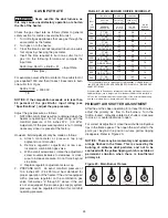
A proper pilot flame is a soft steady flame that
envelops 3/8 to 1/2-inch (9.5 to 12.7 mm) of the
flame sensor tip.

4.

Replace the pilot adjustment cap.

MANIFOLD PRESSURE ADJUSTMENT

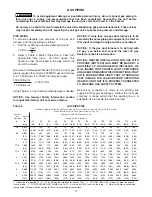
If the manifold pressure requires minor adjustment,
remove the cap from the pressure regulator and turn the
adjustment screw clockwise to increase the pressure, or
counterclockwise to decrease the pressure. The
adjusted manifold pressure should not vary more than
10% from the pressures specified in Table 6.

 Under no circumstances should

combustible material be located within the
clearances specified in this manual. Failure to
provide proper clearance could result in personal
injury or equipment damage from fire.

  2. Turn off the manual gas valve and electrical power

to the gas duct furnace.

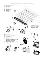
  3. To clean or replace the main burners, remove the

bottom panel or slide out the pullout drawer, and
compress the spring by moving the burner toward
the manifold. Slide the opposite end of the burner
downward from the locating slot while retaining
spring is still compressed. Pull the burners away
from the manifold.

  4. With the burners removed, wire brush the inside

surfaces of the heat exchanger.

  5. Remove any dirt, dust, or other foreign matter from

the burners using a wire brush and/or compressed
air. Ensure that all parts are unobstructed. Inspect
and clean pilot burner if necessary.

  6. Reassemble the gas duct furnace by replacing all

parts in reverse order.

  7. Complete the appropriate unit start-up procedure

as given in the “Operation” section of this manual
(see lighting instruction plate on the access side of
the unit).

  8. Check the burner adjustment. See the “Primary Air

Shutter Adjustment” section of this manual.

  9. Check all gas control valves and pipe connections

for leaks.

10. Check the operation of the automatic gas valve by

lowering the setting of the thermostat, stopping the
operation of the gas duct furnace. The gas valve
should close tightly, completely extinguishing the
flame on the main burners.

11. Check the operation of the pilot safety device by

closing the pilot line valve, extinguishing the pilot
flame. Within one minute the automatic gas valve
should close, extinguishing the flame on the main
burners.

12. Inspect and service the blower section of the

system.

13. Check and test the operational functions of all

safety devices supplied with your unit.

PERIODIC SERVICE

 Open all disconnect switches and

secure in that position before servicing unit.
Failure to do so may result in personal injury or
death from electrical shock.

 Gas tightness of the safety shut-

off valves must be checked on at least an annual
basis.

To check gas tightness of the safety shut-off valves, turn
off the manual valve upstream of the appliance
combination control. Remove the 1/8 inch pipe plug on the
inlet side of the combination control and connect a
manometer to that tapping. Turn the manual valve on to
apply pressure to the combination control. Note the
pressure reading on the manometer, then turn the valve
off. A loss of pressure indicates a leak. If a leak is detected,
use a soap solution to check all threaded connections. If
no leak is found, combination control is faulty and must be
replaced before putting appliance back in service.

NOTICE: The heater and vent system should be
checked once a year by a qualified technician.

 It is the service technician’s

responsibility to check all safety controls!
Check and test the operational functions of all
safety devices supplied with this unit, and
ensure that all are operating effectively. Failure
to do so could result in unsafe conditions and
may result in death, serious injury or property
damage.

All Maintenance/Service info should be recorded
accordingly on the Inspection Sheet provided on back
cover of this manual. Should maintenance be required,
perform the following inspection and service routine:
  1. Inspect the area near the unit to be sure that there

is no combustible material located within the
minimum clearance requirements listed in the
“Installation” section and in Table 4.

MAINTENANCE

Summary of Contents for NATURAL INDOOR GAS-FIRED DUCT FURNACE

Page 1: ...th defects or other reproductive harm INSTALLER S RESPONSIBILITY Installer Please Note This equipment has been test fired and inspected It has been shipped free from defects from our factory However s...

Page 2: ...to in this manual are the ones that were applicable at the time the design was certified In addition the duct furnace may be installed on the downstream side of a cooling unit without need of a bypas...

Page 3: ...k tested by a suitably qualified individual per instructions in this manual Also follow procedures listed on the Gas Equipment Start up sheet located in this manual Use only the fuel for which the hea...

Page 4: ...RH 1 2 1 2 221 664 603 645 816 203 RH 100 225 28 7 8 26 1 2 28 1 8 34 7 8 8 RH 3 4 1 2 OR 3 4 243 733 673 714 886 203 RH 110 250 31 5 8 29 1 4 30 7 8 37 5 8 8 RH 3 4 1 2 OR 3 4 252 803 743 784 956 203...

Page 5: ...5 8 18 1 4 19 7 8 4 26 5 8 1 2 1 2 197 524 464 505 102 676 89 175 23 3 8 21 22 5 8 4 29 3 8 1 2 1 2 216 594 533 575 102 746 98 200 26 1 8 23 3 4 25 3 8 5 32 1 8 1 2 1 2 232 664 603 645 127 816 105 225...

Page 6: ...ater SIZE kW kW kW cu m s Deg C kPa cu m s Deg C Pascals 100 100 50 80 929 80 0 12 2469 30 0 90 29 3 14 6 23 4 0 438 44 0 03 1 165 17 0 22 125 125 62 5 100 1157 80 0 13 3086 30 0 80 36 6 18 3 29 3 0 5...

Page 7: ...allow a minimum of 21 inches 533mm at the bottom of the unit to facilitate servicing the burners and pilot or six inches 152mm if the unit has a side access burner drawer Provision should also be made...

Page 8: ...of mechanical vibration AIR FLOW The installation is to be adjusted to obtain an air throughput within the range specified on the appliance rating plate INSTALLATION COMBUSTION INLET AIR VENTILATION I...

Page 9: ...EOFSAFELYSUPPORTINGITS WEIGHT UNDER NO CIRCUMSTANCES MUST THE GAS LINES VENTING SYSTEM OR THE ELECTRICAL CONDUIT BE USED TO SUPPORT THE HEATER OR ANY OTHER OBJECTS I E LADDER PERSON LEAN AGAINST THE H...

Page 10: ...where drafts may affect the operation of the control 2 Hot areas Areas where the sun s rays radiation or warm air currents may affect control operation 3 Dead areas Areas where air cannot circulate fr...

Page 11: ...mon flue the cross sectional area of the common flue must be equal to the largest vent connection plus 50 of the area of each additional vent connection 3 Provide as long a vertical run of flue at the...

Page 12: ...ired from the venter outlet before installing an elbow in the vent system An elbow should never be attached directly to the venter Use single wall pipe constructed of 26 gauge galvanized steel or mate...

Page 13: ...sfor Structure Termination Locations 4 feet below Door window or any gravity air inlet 4 feet horizontally 1 foot above Forced air inlet within 10 ft 3 feet above Adjoining building or parapet 6 feet...

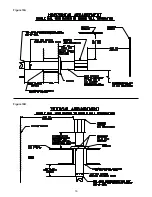
Page 14: ...14 Figure 12A Figure 12B...

Page 15: ...15 Figure 13A Figure 13B...

Page 16: ...Cap At Lowest Point Of Vent System Typ D4072 To Horizontal Flue Vent Termination Reducer Increaser Where Applicable Power Venter Power Venter Tee With Drip Leg Cleanout Cap At Lowest Point Of Vent Sy...

Page 17: ...10 6 9 06 8 07 7 36 6 80 6 23 5 80 5 52 4 96 4 53 4 11 3 82 1 1 4 1 380 1400 950 770 660 580 530 490 460 430 400 360 325 300 280 35 39 6 26 9 21 8 18 7 16 4 15 0 13 9 13 0 12 2 11 3 10 2 9 20 8 50 7...

Page 18: ...ng its full rated capacity as specified in Table 6 A field LP tank regulator must be used to limit the supply pressure to maximum of 14 W C 3 5 kPa All piping should be sized in accordance with the la...

Page 19: ...t Not standard equipment Also refer to Electrical Section Never use an open flame to detect gas leaks Explosive conditions may exist which would result in personal injury or death START UP Open the ma...

Page 20: ...ion Box 7 Pilot Tubing 9 High Limit Switch 10 Pilot Burner Assembly 11 Blocked Vent Spill Switch These safety devices are located on the rear header plate of heat exchanger inlet air side This safety...

Page 21: ...exceed 90 seconds from a cold start Make sure your fan is functioning properly 4 The wall thermostat is a temperature sensitive switch which turns the main gas valve ON or OFF to control the temperat...

Page 22: ...ressure to the main burners f Manual shutoff valve for service and long term shut down Separate from the automatic valve on some models 2 The high limit switch interrupts the flow of electric current...

Page 23: ...of the Heat Exchanger Air Inlet Side 14 Blocked Vent Spill Switch Located in the Upper Right Corner of the Unit Access Side Figure 19 Burner Components IntermIttent Pilot Ignition Also refer to Figure...

Page 24: ...3 5 inches W C 0 9 kPa Adjustment of the pressure regulator is not normally necessary since it is preset at the factory However field adjustment may be made as follows a Attach manometer at pressure t...

Page 25: ...e operation of the gas duct furnace The gas valve should close tightly completely extinguishing the flame on the main burners 11 Check the operation of the pilot safety device by closing the pilot lin...

Page 26: ...Figure 23 Burner Assembly Parts Figure 21 Duct Furnace Components Figure 22 Burners Controls FLAME CARRYOVER MAIN BURNER PACKAGED GAS VALVE BURNER DRAWER PILOT BURNER ASSEMBLY PARTS PILOT OBSERVATION...

Page 27: ...BRACKET JUNCTION BOX 9 SCREW S T 10 SCREW MACHINE L 3 4 11 NUT KEPS EXT LOCKWASHER 12 AIR PRESSURE SWITCH 13 DRILL SCREW 14 JUNCTION BOX ASSEMBLY REF NO DESCRIPTION 15 SNAP BUSHING 16 RELAY 17 STRAIG...

Page 28: ...from the Power Venter Blower Housing Item 8 6 Remove the Blower Wheel Item 9 from the motor shaft by removing the set screw Item 14 using a 1 8 Allen Wrench 7 Remove the three Motor Mounting Nuts Item...

Page 29: ...piping is inadequately sized Refer to Installation 5 Clean pilot orifice Refer to Oper ation 6 Eliminate drafts Refer to Installation 7 Refer to Installation 1 Open all manual gas valves 2 Replace fus...

Page 30: ...s valves 2 Increase size of pilot flame Refer to Operation 3 Purge air from gas supply 4 Follow lighting instruction label adjacent to gas valve 5 Remove pilot orifice Clean with compressed air or sol...

Page 31: ...2 Replace motor 3 Check for 24V across 1 and 3 terminals on fan relay If 24V is present jumper terminals numbered 2 and 4 If motor runs the relay is defective and must be replaced If 24V is not prese...

Page 32: ...tor voltage with fan running Should be 115 volts AC 3 Refer to Operation 1 Close thermostat contacts 2 Check for 24V across 24V terminals of S8600 3 Set gap to 0 1 4 Replace pilot assembly 1 Check all...

Page 33: ...ing removal or reinstallation of the defective Product or parts thereof c to any damage due to corrosion by chemicals including halogenated hydrocarbons precipitated in the air d to any workmanship of...

Page 34: ...34 NOTES...

Page 35: ...e controls GAS EQUIPMENT START UP GENERAL With power and gas off Make certain all packing has been removed Tighten all electrical terminals and connections Check damper linkages for tightness Check al...

Page 36: ......

Reviews: